Dear all,
I updated this blog to a new platform, please update your bookmarks to:
https://reddogsmodels.wordpress.com/
I will not update this blog anymore
Cheers all
Friday, April 28, 2017
Friday, February 17, 2017
Kinetic vs Hasegawa vs Tamiya F-16 1/48
A while ago, I was asked to build two 1/48 F-16 Belgian air force model.
One old F-16A block 15 and one more modern F-16A MLU. The earlier model will be displayed in flight and the later MLU model will be displayed as an F-16 deployed in Afghanistan.
Looking around for suitable models for the project, I looked at the F-16A from Hasegawa but quickly realised that building a MLU out of this wouldn't be suitable - although the decoration provided in the box should clearly be a MLU. No big deal for me anyway as I need an earlier F-16A model.
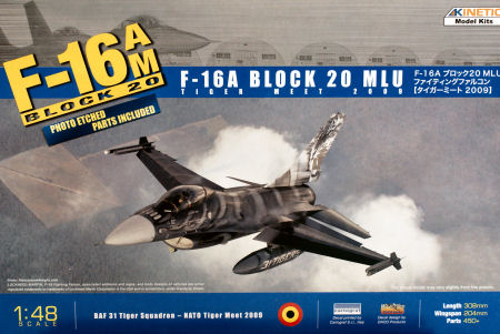
Looking for a MLU model, I considered Tamiya as it's a pretty sure value, but again converting to MLU wasn't going to be easy as Tamiya does multi version (block 25/32, aggressor, block50) but strangely enough no MLU that I know of. Kinetic came to the rescue with a specific MLU model.
With both model selected; let's get on building.
1. Cockpit
Like most modeller this is where I often start.
Hasegawa cockpit is very simplistic but assembled in a glimpse. It's made of 9 pieces pilot excluded. The pilot is available though and will be used. The IP is the older block 15 while surprisingly the instructions clearly show a MLU IP. I looked deeply in the box of the model, there is no MLU IP included. The differences are very noticeable though, the MLU has two MFDs and an ICP while the block 15 has no MFDs but a SMS panel on the left and a radar screen on the centre console. I don't really care as I'm building a F-16A prior to Mid Life Upgrade, but be warned if you want to build a MLU out of it.
The flight controls are very gross and frankly needs to be replaced (Luckily the Kinetic box offers two sets of Hotas). The seat is very simplistic and oversized and since it's the most visible part of the cockpit, I'd replace it as well with a resin aftermarket.
There is no detail on the sidewall (armrests, canopy spiders, ...) and it's a chance we can not see the rudder because they must be at least 3 times bigger than the real F-16 ones.
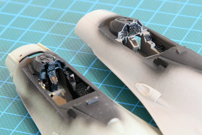
The Kinetic cockpit is much better detailed but a pain to build, especially the seat. It's barely possible to assemble it and even less possible to slide it into the cockpit once assembled...
The surface details of the cockpit are much better than Hasegawa's. The centre panel is accurate for a MLU, except the ICP which is very flat and could use a bit more details.
Flight controls are well detailed and the throttle is provided in the CUTOFF position (lifted almost vertically) which is very accurate for a model with the engine not running. Surface detail on the panel allows easy drybrush to highlight the details. Armrest is supplied but sadly no spider. Since the armrest is on a duplicate tree it easy to create a spider from the extra armrest. As the canopy will be open, the spider needs to be visible.
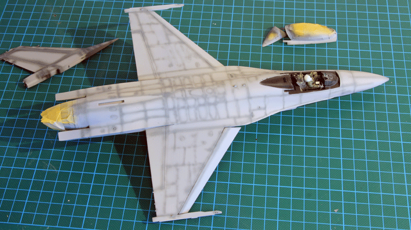
Cockpit assembly into the top fuselage didn't present any problem. I just had to go against the instructions and glued the IP on the glareshield first rather than gluing the IP on the cockpit floor. The fit was better this way.
2. Gear Bay
The Hasegawa gear bays are very sparse and devoid of detail. Luckily the in-flight display will allow me to close the gear doors on the model avoiding the problem. But there is no question that if I had to build the model on its gear, I'd seek an aftermarket product for the gear bay. Closing the gear doors flush didn't create any issue, which is worth mentioning as it's rarely the case.
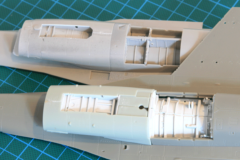
Kinetic has a bit more details but as usual the plumbing is lacking. So detailing will be required.
The big gear bay surprise came well after having assembled and painted the model. When I glued the main gear legs in the gear bay I noticed that the aircraft was not level when viewed from the front. The right wingtip was almost 5 mm lower than the left wingtip. Yep, 5mm !!!
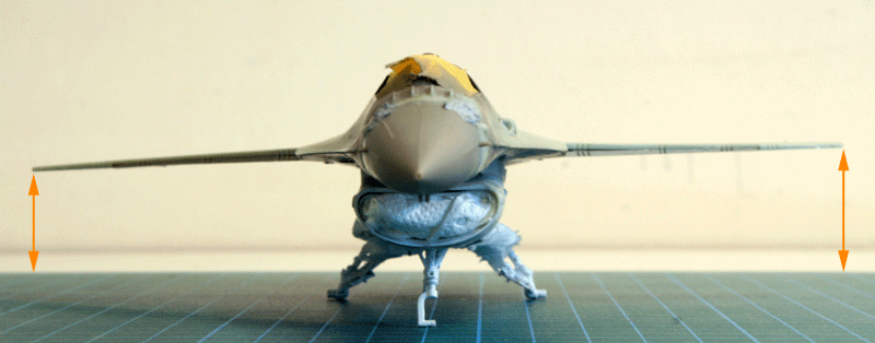
I traced back the issue to the way the main gear bay is attached inside the fuselage. There are 4 square locating pins that needs to be inserted into 4 square holes. I probably wasn't careful enough and didn't test correctly that the gear bay was fitting nicely into all 4 locating holes. It's the biggest issue with this model, the fit of the locating holes are always creating fitting issues. I couldn't correct this one, especially after all the trouble I went through to sand the fuselage smooth after the horrible fit. I decided to leave it and deal with it later on, trying to correct it at the wheel level.
3. Seats
As I said above, both the Hasegawa and Kinetic seats need to be replaced.
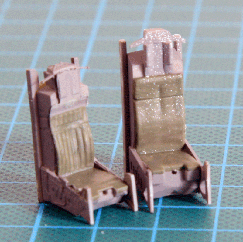
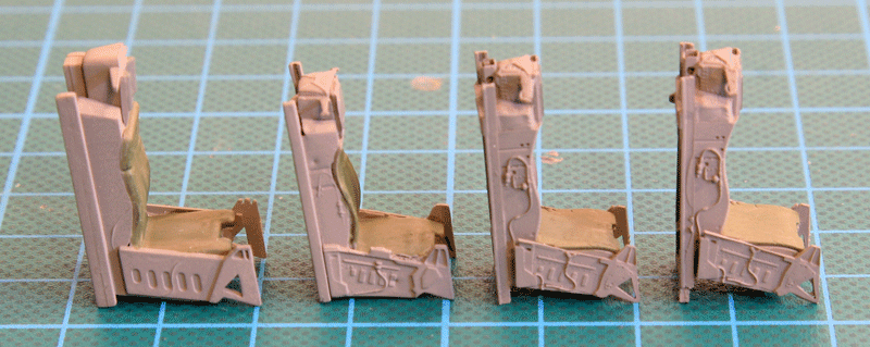
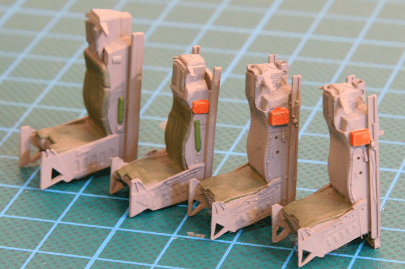
Considering the plethora of aftermarket seats, I chose the Eduard Brassin offering because they had an early and late version of the Aces 2 which were perfectly suiting my early A and late MLU models. The Brassin seats are indeed gorgeous. the smallest details are provided either in resin or PE, placards are full harness are provided. They were quickly assembled and painted. The late model will get the full harness and the early seat will get a pilot seating so the seatbelts will be placed according to the pilot model.
I didn't notice much difference between the early and late style offering from Brassin. To be honest I expected the late model to have the retractable pitot and the early seat the fixed pitot. But no the only difference I could notice was that the late seat had the sheepskin cushion as an option which isn't available in the early seat. It's a shame about the pitot because it is a very visible detail in the F-16 cockpit.
Although the detail is pretty high, I was expecting more homework from Brassin and I was really disappointed with the lack of differences between the two offerings.
I ordered the Brassin seats as well as the late F-16 MLU wheels and the Sniper pod from the Eduard website. The online ordering was very slow and took more than two weeks from Eduard Czech headquarters to my home in Belgium. I'd say there is room for improvement.
4. Assembly
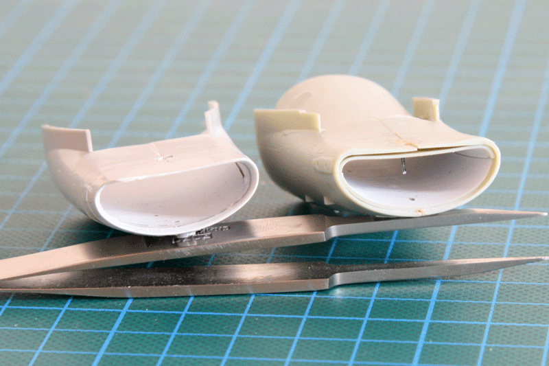
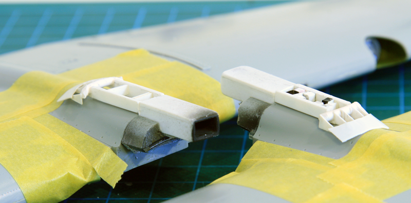
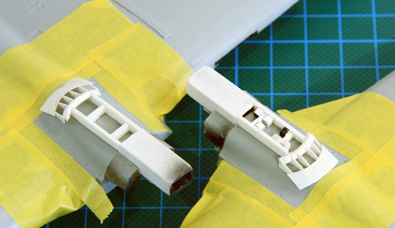
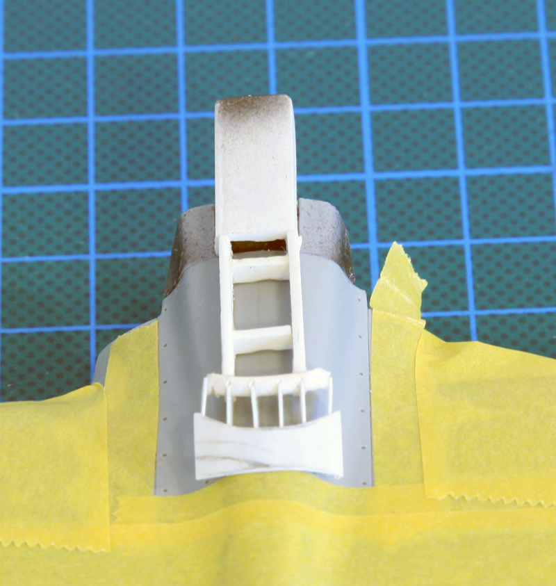
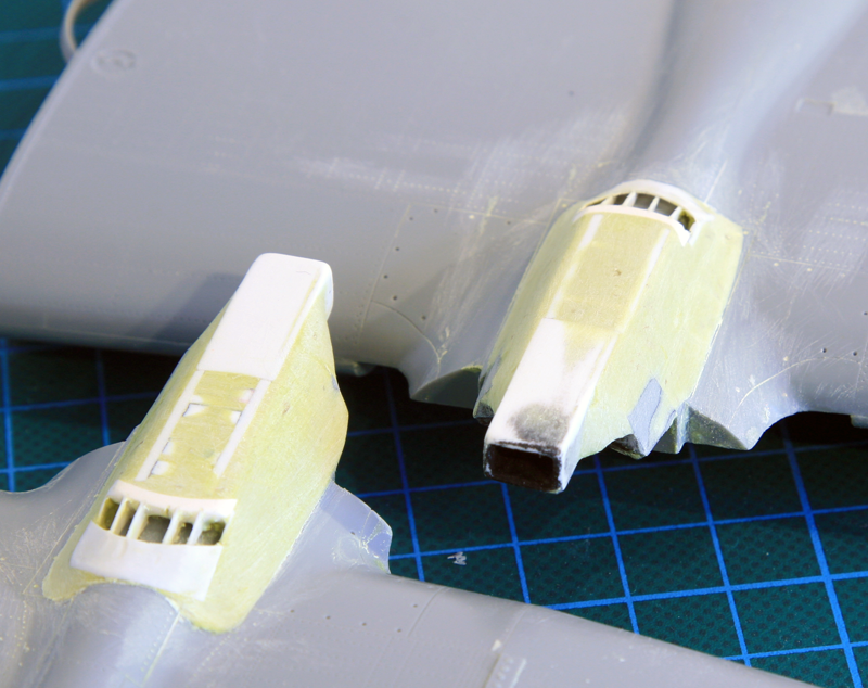
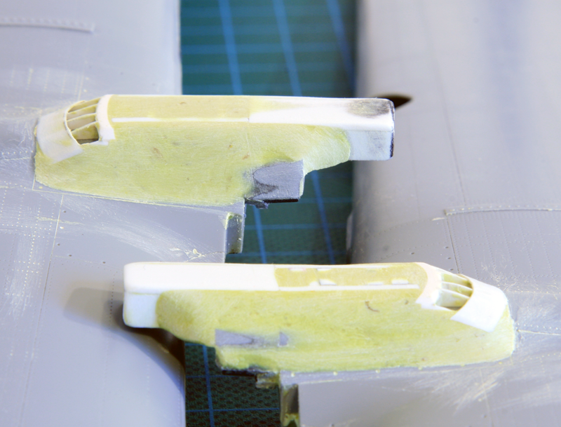
The biggest issue of all F-16 models is obviously the intakes. These two are no different. The Hasegawa (seen left on the image below ends up in a simple plastic wall with no compressor blade visible. It's far from being seamless and the way it's assembled makes it impossible to hide the joints as there is no intake duct. That said, it's not too much visible and I can live with it.
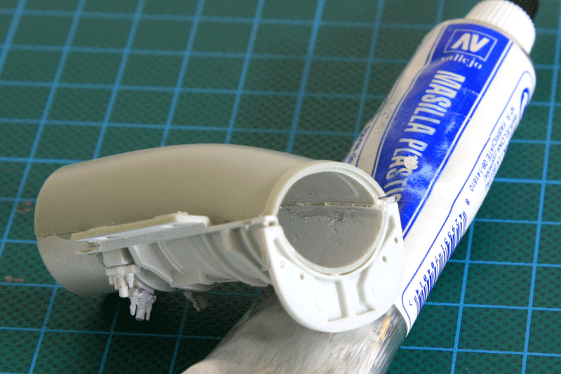
I was surprised with the Kinetic intake as I was expecting much more problems but it went relatively easy. Vallejo water putty was applied in the intake seams and wiped smooth with a slightly watered tissue.
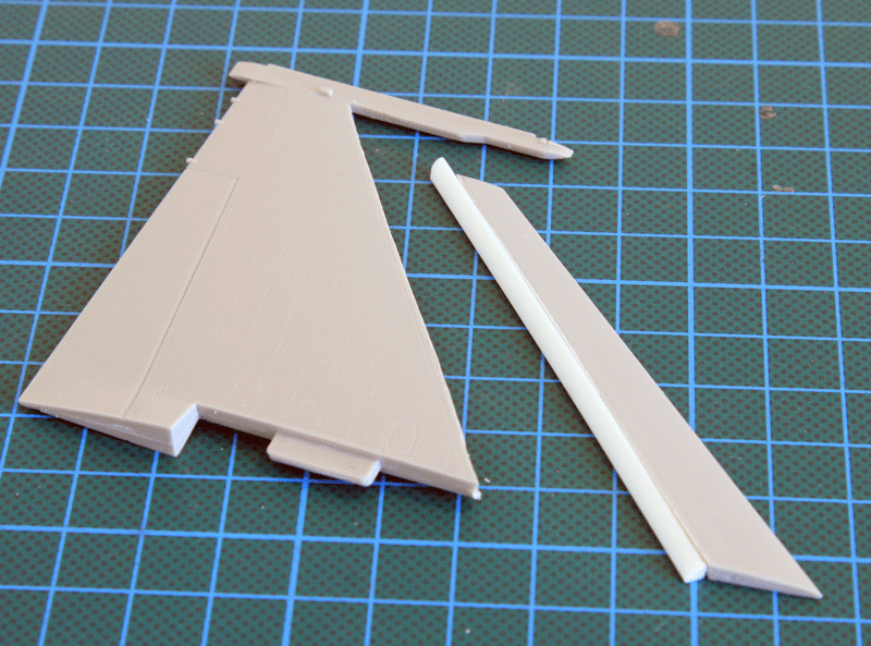
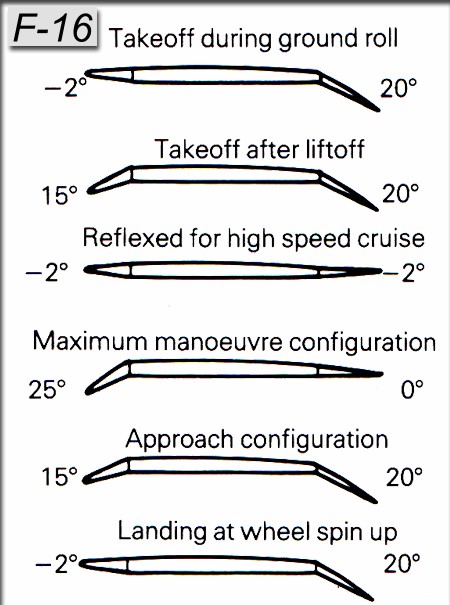
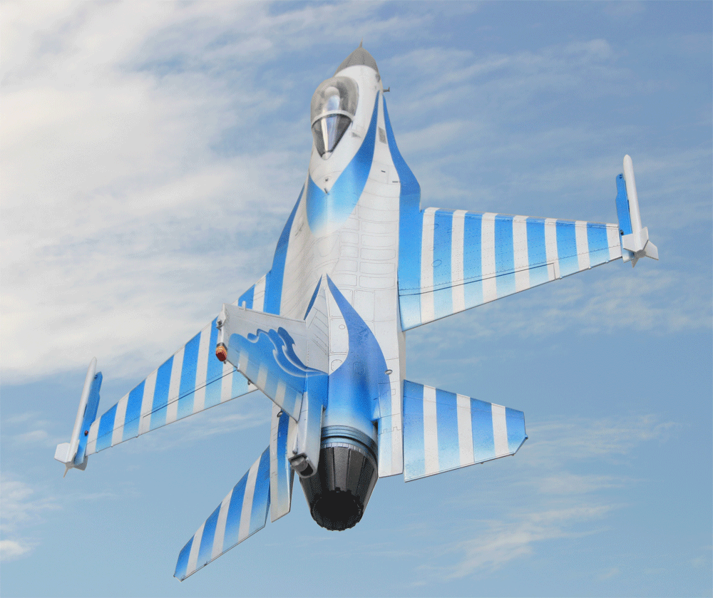
The Hasegawa model fits nicely and is very quickly assembled. Unfortunately it's a clean configuration with no possibility to lower the LEF (Leading Edge Flaps) or TEF (Trailing Edge Flaps). Well F-16 on the ground have the LEF level or pointing up 2-3° and the TEF can be lowered. But in flight the TEF will most of the time be level and the LEF will be down as the aircraft manoeuvers. Since my inflight display is an airshow model I have to extend the LEF and I can leave the TEF as they are.
Of course the Kinetic offers the possibility to lower both TEF and LEF but that one will be on the ground, so I will keep the LEF straight 2-3° up and lower the TEF.
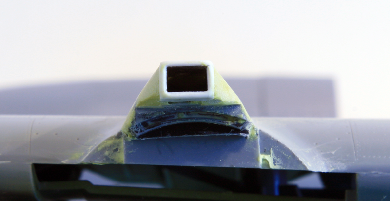
The real downfall of the Kinetic kit happened around the nose. The nose side panels are molded separately due to the different configurations possible but they fit very badly on the fuselage. The nose is very well detailed but a lot of the detail around the nose section will be lost due to intense puttying and sanding required to have the side panels smooth.
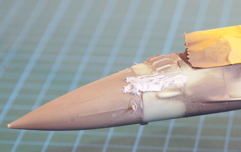
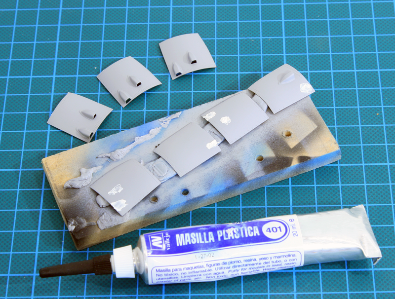
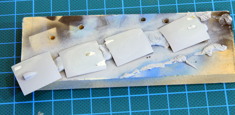
Kinetic provides the reinforcement plates for the MLU and these are a welcome addition. They are a bit thick and the two nose reinforcement plates are very hard to shape correctly. Luckily these actually hide a bit the sanding mess around the nose antennas. They should be replaced with thinner plasticard bits easier to shape accordingly. I nevertheless used the top fuselage reinforcement plates.
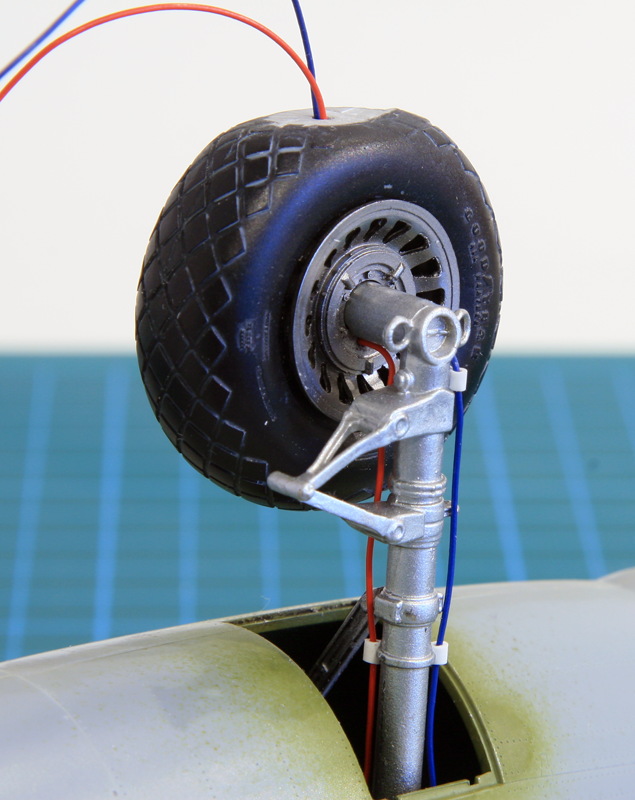
The Kinetic wheels have been replaced by Brassin wheels. The Kinetic's are way oversized and that is very visible on the finished model.
The Kinetic canopy is not easy to display open. A lot of thinning will be required on the part supporting the opened transparent canopy.
5. Painting
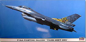
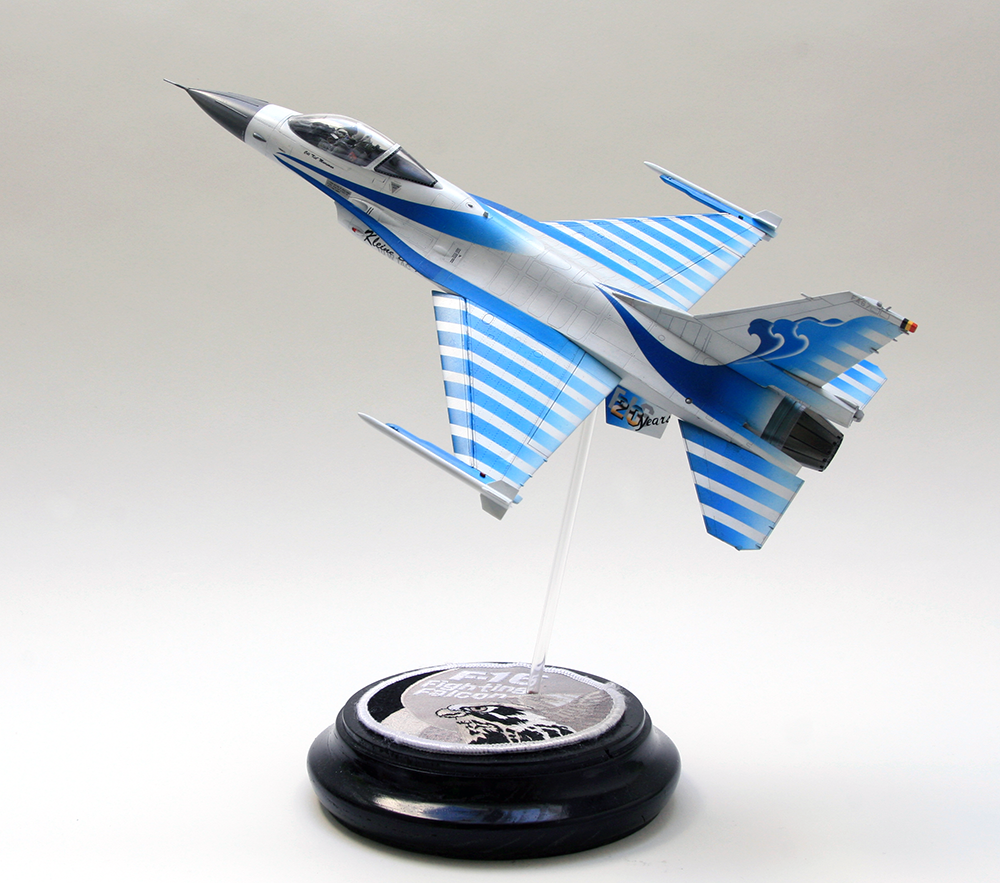
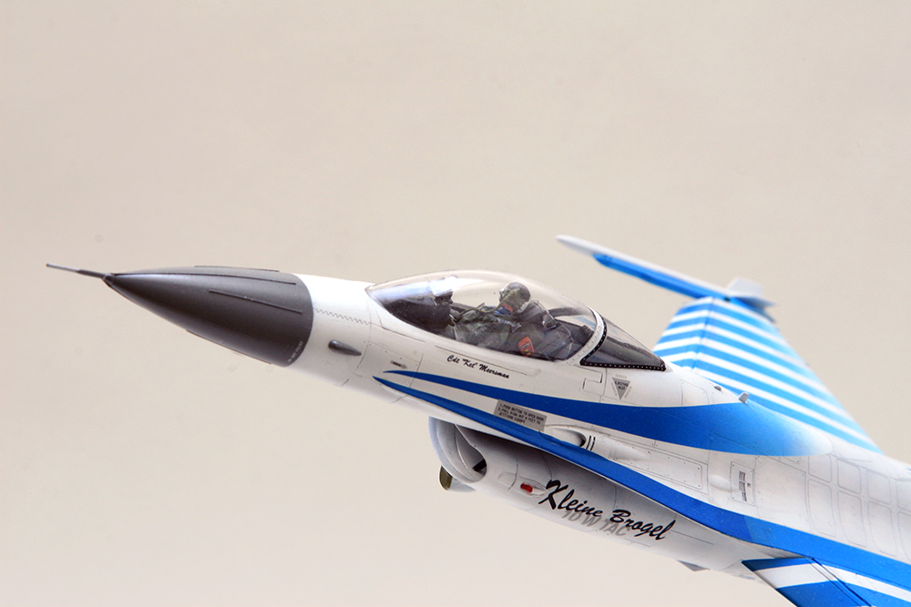
Both model will greatly differ in painting. The late MLU Kinetic kit will be an operational Belgian F-16 in Afghanistan while the early Hasegawa will be a F-16A specially painted as the white falcon for the 1998 airshow season commemorating 20 years of flying the F-16 in the Belgian air force.
Both models received a pre-shade of the panel lines. The white falcon was lightly pre-shaded in grey due to the overall white paint. The MLU was pre-shaded in black as usual.
The cockpit of the Hasegawa model was finished and sealed closed before the first coat of white paint. I used Tamiya XF-2 acrylic paint mixed with X-22 gloss varnish and applied multiple thin coats on the whole model.
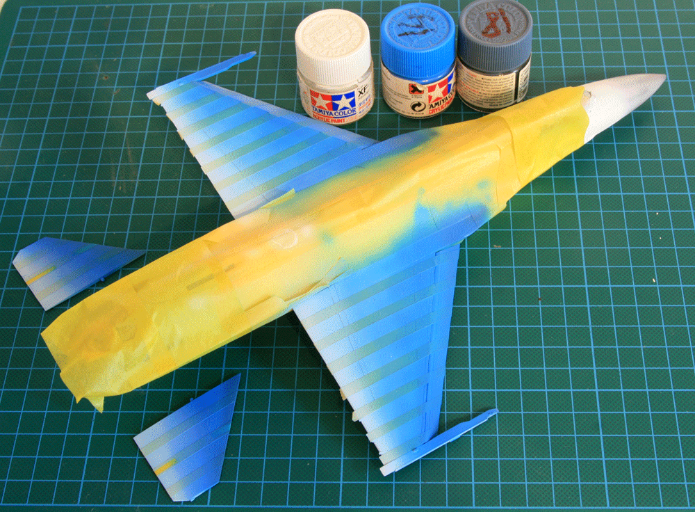
Daco provides a full sheet for the white falcon but I decided to paint as much as possible rather than using the thick decals which will hide many details on the wings and stabs. The big challenge was to paint the colour gradient from bright blue to white.
Using the decals as template, the aircraft was masked and blue paint was spayed. The blue was varying from XF-14+XF18 at the front to pure XF-14 in the middle and XF-14+ white close to the trailing edge of the wings and stabs.
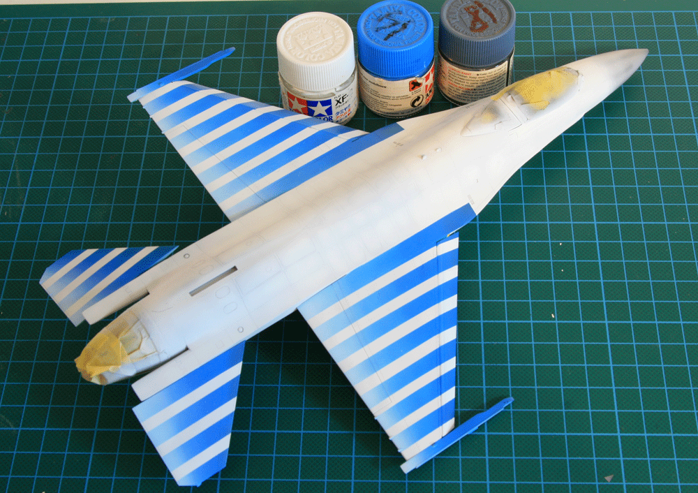
The rest of the blue lines and shapes were applied as decals from Daco sheet 48-47, but not before a couple coats of highly gloss varnish to prevent their silvering. The large part decals adhered to the contours of the model thanks to Daco decal strong solution.
The nose of the aircraft was painted with Gunze H307 & H317 which contrasts nicely with the white overall paint. The model received a very light wash of brown before the final coat of semi-gloss varnish was applied.
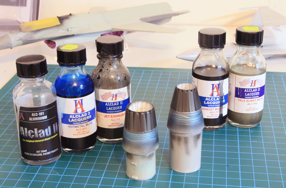
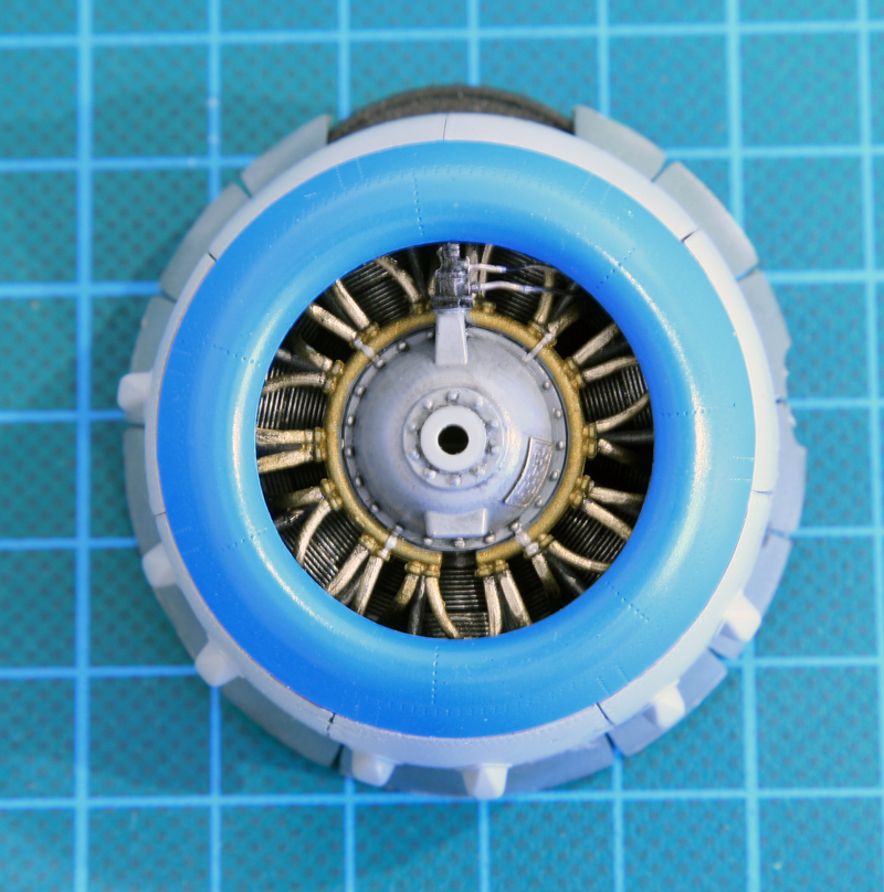
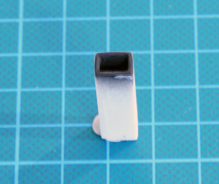
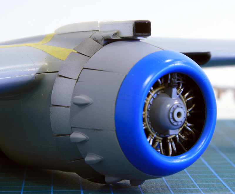
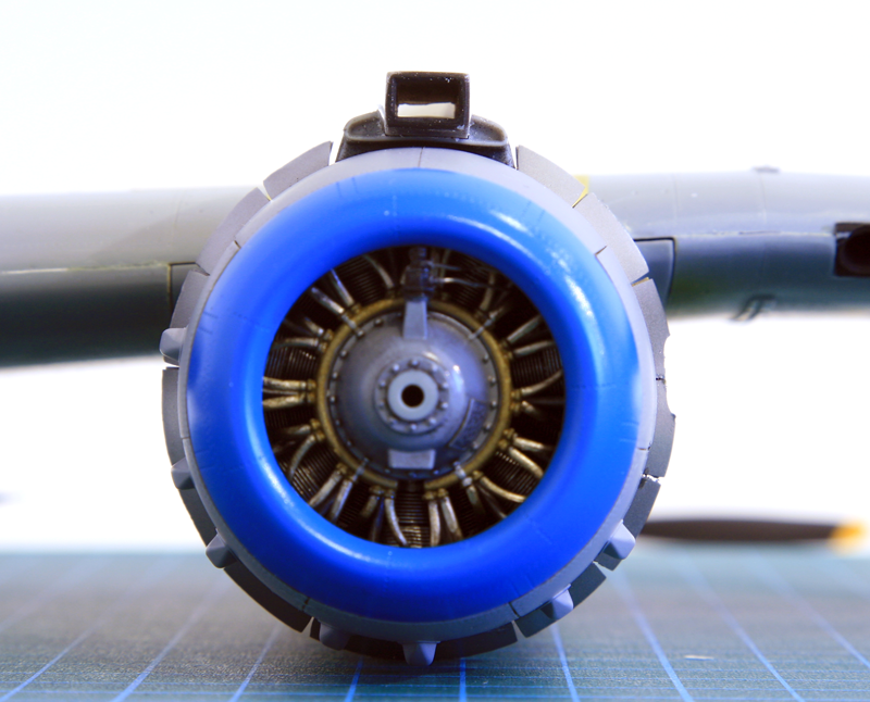
The Hasegawa exhaust was replaced by a closed nozzle found in the stash box. The Kinetic exhaust was deemed good enough to be used as is. I painted both with variation of alclad starting with aluminium, then hot metal blue. The nozzle itself was given a coat of jet exhaust and exaust manifold then masked and a mist of pale burnt metal was sprayed. This technique leaves the part of the petals that are not visible when the nozzle is closed darker and gives a nice depth to the part.
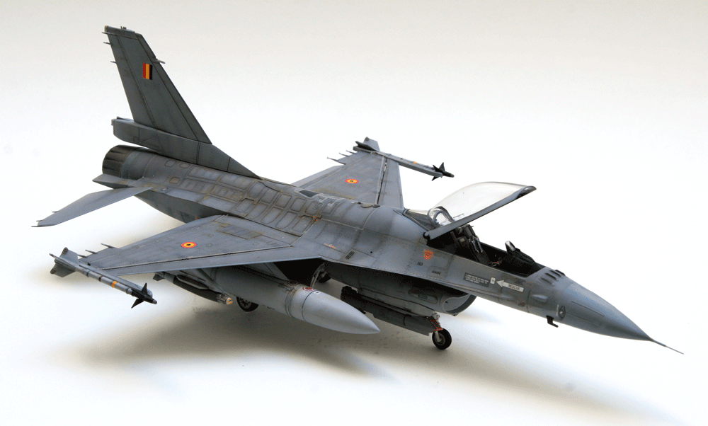
The MLU was painted in the usual F-16 grey, which for Belgians aircraft is still the old 3 tone greys: H308 for under surfaces, H306 for intake top and tail and nose section and H305 for the top fuselage and wings.
After painting the model was directly weathered with different shades of grey giving an operationnal status to the airframe. Inside panels were painted with a lighter shade of grey and then the different colours were subtly blended together. Decals will be again provided by Daco which are always a bit on the thick side and prone to silvering. So heavy gloss varnish will be used before decaling.
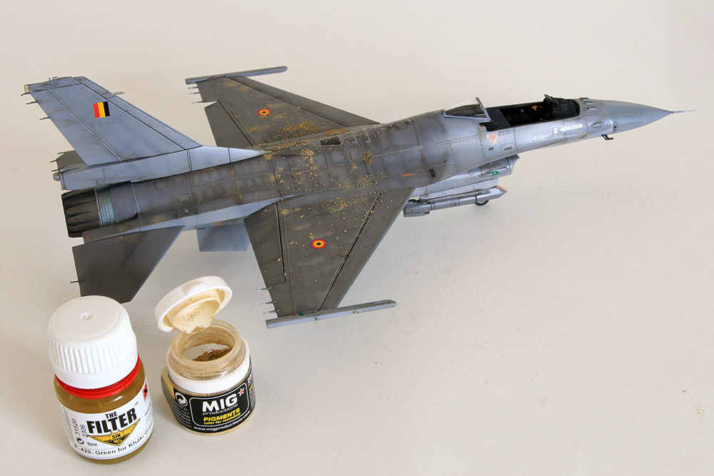
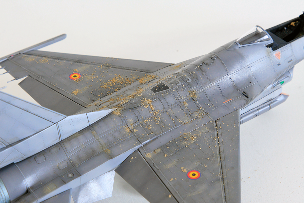
The model received the usual dark brown wash before a very specific filter of yellow and light brown dust pigment to replicate the very persistent wheat flour like dust of Bagram airbase. These Afghanistan specific weathering were mostly concentrated on the top central surfaces of the model.
The whole model was then sealed with thin coat of matt Vallejo varnish.
6. Weapons
Obviously the white falcon doesn't have any weapon. The kit's sidewinders were quickly converted to smoke-winder by simply removing the forward fins. Normally the smoke-winder are larger than the sidewinder and needs a specific exhaust but I didn't bother for this occasion. Luckily I chose an airshow configuration because the Hasegawa boxes don't include any offensive air to ground weapons.
The operational airframe carries the usual CAS load of the Belgian F-16 in Afghanistan. Two wing bags, a GBU-12 laser guided bomb and a GPS guided J-DAM on the PIDS pylons, two AIM-9 sidewinder (you can hardly see BAF F-16 carrying two in Afghanistan) and the Sniper targeting pod on the right chin pylon assembled and painted according to Brassin instructions.
The kinetic kit includes plenty of weapons which are very welcome for this and future projects.
7. Conclusions
The Hasegawa kit comes with no surprise and except for my in flight requirement was very easy to build. The kit though lacks a bit of flexibility which basically shows its age. Cutting out the LEF wasn't the easiest thing to do but tremendously add to the dynamic pose of the model. Another challenge was to source a closed nozzle for a dry thrust aircraft, but I was lucky on that one.
On the other hand closing the gear doors and the canopy didn't pose any real issue, which is quite uncommon. The biggest issue of the kit regardless of the configuration is the intake as it is often the case.
I had high hopes for the kinetic kit due to the flexibility of the configuration, the details and the weapon options. Unfortunately all this was toned down by the multiple and serious fitting issues of the kit. In fairness to Kinetic the F-16 is one of their very early model and I heard that their latest kits are much better. I will have to try one to be convinced. Unfortunately the next one I plan on building is another early model of kinetic: the E-2C.
Although this kit was very bad, i am not unhappy with the end result. Proof that with dedication the modeller can overcome almost anything - at least until the model fly for real... not driven by jet fuel but rather modeller frustration !
Sure the finished model has flaws and it's far from being perfect, but it came close to never being completed.
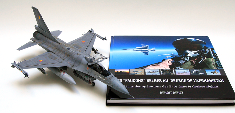
The book on the picture above is a great ressource for the Belgian F-16 operations in Afghanistan and helped a lot with choosing the correct configuration, weapon and weathering. I probably couldn't finish the model without it.
Not only for the documentation it provided but mostly for the account of the guys being there that kept me interested and focused on the difficult model.
One old F-16A block 15 and one more modern F-16A MLU. The earlier model will be displayed in flight and the later MLU model will be displayed as an F-16 deployed in Afghanistan.
Looking around for suitable models for the project, I looked at the F-16A from Hasegawa but quickly realised that building a MLU out of this wouldn't be suitable - although the decoration provided in the box should clearly be a MLU. No big deal for me anyway as I need an earlier F-16A model.
Looking for a MLU model, I considered Tamiya as it's a pretty sure value, but again converting to MLU wasn't going to be easy as Tamiya does multi version (block 25/32, aggressor, block50) but strangely enough no MLU that I know of. Kinetic came to the rescue with a specific MLU model.
With both model selected; let's get on building.
1. Cockpit
Like most modeller this is where I often start.
Hasegawa cockpit is very simplistic but assembled in a glimpse. It's made of 9 pieces pilot excluded. The pilot is available though and will be used. The IP is the older block 15 while surprisingly the instructions clearly show a MLU IP. I looked deeply in the box of the model, there is no MLU IP included. The differences are very noticeable though, the MLU has two MFDs and an ICP while the block 15 has no MFDs but a SMS panel on the left and a radar screen on the centre console. I don't really care as I'm building a F-16A prior to Mid Life Upgrade, but be warned if you want to build a MLU out of it.
The flight controls are very gross and frankly needs to be replaced (Luckily the Kinetic box offers two sets of Hotas). The seat is very simplistic and oversized and since it's the most visible part of the cockpit, I'd replace it as well with a resin aftermarket.
There is no detail on the sidewall (armrests, canopy spiders, ...) and it's a chance we can not see the rudder because they must be at least 3 times bigger than the real F-16 ones.
The Kinetic cockpit is much better detailed but a pain to build, especially the seat. It's barely possible to assemble it and even less possible to slide it into the cockpit once assembled...
The surface details of the cockpit are much better than Hasegawa's. The centre panel is accurate for a MLU, except the ICP which is very flat and could use a bit more details.
Flight controls are well detailed and the throttle is provided in the CUTOFF position (lifted almost vertically) which is very accurate for a model with the engine not running. Surface detail on the panel allows easy drybrush to highlight the details. Armrest is supplied but sadly no spider. Since the armrest is on a duplicate tree it easy to create a spider from the extra armrest. As the canopy will be open, the spider needs to be visible.
Cockpit assembly into the top fuselage didn't present any problem. I just had to go against the instructions and glued the IP on the glareshield first rather than gluing the IP on the cockpit floor. The fit was better this way.
2. Gear Bay
The Hasegawa gear bays are very sparse and devoid of detail. Luckily the in-flight display will allow me to close the gear doors on the model avoiding the problem. But there is no question that if I had to build the model on its gear, I'd seek an aftermarket product for the gear bay. Closing the gear doors flush didn't create any issue, which is worth mentioning as it's rarely the case.
Kinetic has a bit more details but as usual the plumbing is lacking. So detailing will be required.
The big gear bay surprise came well after having assembled and painted the model. When I glued the main gear legs in the gear bay I noticed that the aircraft was not level when viewed from the front. The right wingtip was almost 5 mm lower than the left wingtip. Yep, 5mm !!!
I traced back the issue to the way the main gear bay is attached inside the fuselage. There are 4 square locating pins that needs to be inserted into 4 square holes. I probably wasn't careful enough and didn't test correctly that the gear bay was fitting nicely into all 4 locating holes. It's the biggest issue with this model, the fit of the locating holes are always creating fitting issues. I couldn't correct this one, especially after all the trouble I went through to sand the fuselage smooth after the horrible fit. I decided to leave it and deal with it later on, trying to correct it at the wheel level.
3. Seats
As I said above, both the Hasegawa and Kinetic seats need to be replaced.
- The Hasegawa is oversized and very simplistic.
- The Kinetic is very well detailed but so hard to assemble and it's almost impossible to slide into the cockpit.
Considering the plethora of aftermarket seats, I chose the Eduard Brassin offering because they had an early and late version of the Aces 2 which were perfectly suiting my early A and late MLU models. The Brassin seats are indeed gorgeous. the smallest details are provided either in resin or PE, placards are full harness are provided. They were quickly assembled and painted. The late model will get the full harness and the early seat will get a pilot seating so the seatbelts will be placed according to the pilot model.
I didn't notice much difference between the early and late style offering from Brassin. To be honest I expected the late model to have the retractable pitot and the early seat the fixed pitot. But no the only difference I could notice was that the late seat had the sheepskin cushion as an option which isn't available in the early seat. It's a shame about the pitot because it is a very visible detail in the F-16 cockpit.
Although the detail is pretty high, I was expecting more homework from Brassin and I was really disappointed with the lack of differences between the two offerings.
I ordered the Brassin seats as well as the late F-16 MLU wheels and the Sniper pod from the Eduard website. The online ordering was very slow and took more than two weeks from Eduard Czech headquarters to my home in Belgium. I'd say there is room for improvement.
4. Assembly
The biggest issue of all F-16 models is obviously the intakes. These two are no different. The Hasegawa (seen left on the image below ends up in a simple plastic wall with no compressor blade visible. It's far from being seamless and the way it's assembled makes it impossible to hide the joints as there is no intake duct. That said, it's not too much visible and I can live with it.
The Kinetic intake is modelled along the Tamiya parts and provide the extra advantage to have the lip separated. That makes the painting process much easier as the lip is usually the fuselage colour inside the intake which is a real pain to paint right. The lip can be painted grey and glued at the later stage providing the perfect contrast between the intake white and the fuselage colour. No hassle solution, perfect!
The Hasegawa model fits nicely and is very quickly assembled. Unfortunately it's a clean configuration with no possibility to lower the LEF (Leading Edge Flaps) or TEF (Trailing Edge Flaps). Well F-16 on the ground have the LEF level or pointing up 2-3° and the TEF can be lowered. But in flight the TEF will most of the time be level and the LEF will be down as the aircraft manoeuvers. Since my inflight display is an airshow model I have to extend the LEF and I can leave the TEF as they are.
Of course the Kinetic offers the possibility to lower both TEF and LEF but that one will be on the ground, so I will keep the LEF straight 2-3° up and lower the TEF.
The LEF were cut of the Hasegawa wings with a scalpel after both upper and lower wing have been glued together. A half round was glued to the LEF and sanded to shape. The innards of the wing were sanded with a triangular file and the LEF was then repositioned on the wing in the 25° down position (max manoeuvering). The rest of the Hasegawa model was assembled without further problem.
The kinetic assembly was a bit more complicated as expected. The parts are cut in the same way as the 1/48 Tamiya F-16 but not as precise and with a lot of fitting issues. One of them is the very visible joint on the upper fuselage which is cut in two just in front of the AAR door. The joint needs putty and sanding and that of course will destroy the engraving of many panel lines. I usually fix this in two steps:
- I protect as many panel lines as possible with masking tape.
- I then apply putty (usually Tamiya putty) and then clean the excess of putty with nail remover before the putty dries away. This avoids the need for the sanding step but the nail remover will attack the plastic so you can not do multiple passes. Another less aggressive method is to use water based Vallejo putty which can then be swiped flat with water.
The Kinetic wheels have been replaced by Brassin wheels. The Kinetic's are way oversized and that is very visible on the finished model.
The Kinetic canopy is not easy to display open. A lot of thinning will be required on the part supporting the opened transparent canopy.
5. Painting
Both model will greatly differ in painting. The late MLU Kinetic kit will be an operational Belgian F-16 in Afghanistan while the early Hasegawa will be a F-16A specially painted as the white falcon for the 1998 airshow season commemorating 20 years of flying the F-16 in the Belgian air force.
Both models received a pre-shade of the panel lines. The white falcon was lightly pre-shaded in grey due to the overall white paint. The MLU was pre-shaded in black as usual.
The cockpit of the Hasegawa model was finished and sealed closed before the first coat of white paint. I used Tamiya XF-2 acrylic paint mixed with X-22 gloss varnish and applied multiple thin coats on the whole model.
Daco provides a full sheet for the white falcon but I decided to paint as much as possible rather than using the thick decals which will hide many details on the wings and stabs. The big challenge was to paint the colour gradient from bright blue to white.
Using the decals as template, the aircraft was masked and blue paint was spayed. The blue was varying from XF-14+XF18 at the front to pure XF-14 in the middle and XF-14+ white close to the trailing edge of the wings and stabs.
The nose of the aircraft was painted with Gunze H307 & H317 which contrasts nicely with the white overall paint. The model received a very light wash of brown before the final coat of semi-gloss varnish was applied.
The Hasegawa exhaust was replaced by a closed nozzle found in the stash box. The Kinetic exhaust was deemed good enough to be used as is. I painted both with variation of alclad starting with aluminium, then hot metal blue. The nozzle itself was given a coat of jet exhaust and exaust manifold then masked and a mist of pale burnt metal was sprayed. This technique leaves the part of the petals that are not visible when the nozzle is closed darker and gives a nice depth to the part.
The MLU was painted in the usual F-16 grey, which for Belgians aircraft is still the old 3 tone greys: H308 for under surfaces, H306 for intake top and tail and nose section and H305 for the top fuselage and wings.
After painting the model was directly weathered with different shades of grey giving an operationnal status to the airframe. Inside panels were painted with a lighter shade of grey and then the different colours were subtly blended together. Decals will be again provided by Daco which are always a bit on the thick side and prone to silvering. So heavy gloss varnish will be used before decaling.
The model received the usual dark brown wash before a very specific filter of yellow and light brown dust pigment to replicate the very persistent wheat flour like dust of Bagram airbase. These Afghanistan specific weathering were mostly concentrated on the top central surfaces of the model.
6. Weapons
Obviously the white falcon doesn't have any weapon. The kit's sidewinders were quickly converted to smoke-winder by simply removing the forward fins. Normally the smoke-winder are larger than the sidewinder and needs a specific exhaust but I didn't bother for this occasion. Luckily I chose an airshow configuration because the Hasegawa boxes don't include any offensive air to ground weapons.
The operational airframe carries the usual CAS load of the Belgian F-16 in Afghanistan. Two wing bags, a GBU-12 laser guided bomb and a GPS guided J-DAM on the PIDS pylons, two AIM-9 sidewinder (you can hardly see BAF F-16 carrying two in Afghanistan) and the Sniper targeting pod on the right chin pylon assembled and painted according to Brassin instructions.
The kinetic kit includes plenty of weapons which are very welcome for this and future projects.
7. Conclusions
The Hasegawa kit comes with no surprise and except for my in flight requirement was very easy to build. The kit though lacks a bit of flexibility which basically shows its age. Cutting out the LEF wasn't the easiest thing to do but tremendously add to the dynamic pose of the model. Another challenge was to source a closed nozzle for a dry thrust aircraft, but I was lucky on that one.
On the other hand closing the gear doors and the canopy didn't pose any real issue, which is quite uncommon. The biggest issue of the kit regardless of the configuration is the intake as it is often the case.
Sure the finished model has flaws and it's far from being perfect, but it came close to never being completed.
The book on the picture above is a great ressource for the Belgian F-16 operations in Afghanistan and helped a lot with choosing the correct configuration, weapon and weathering. I probably couldn't finish the model without it.
Not only for the documentation it provided but mostly for the account of the guys being there that kept me interested and focused on the difficult model.
Monday, July 25, 2016
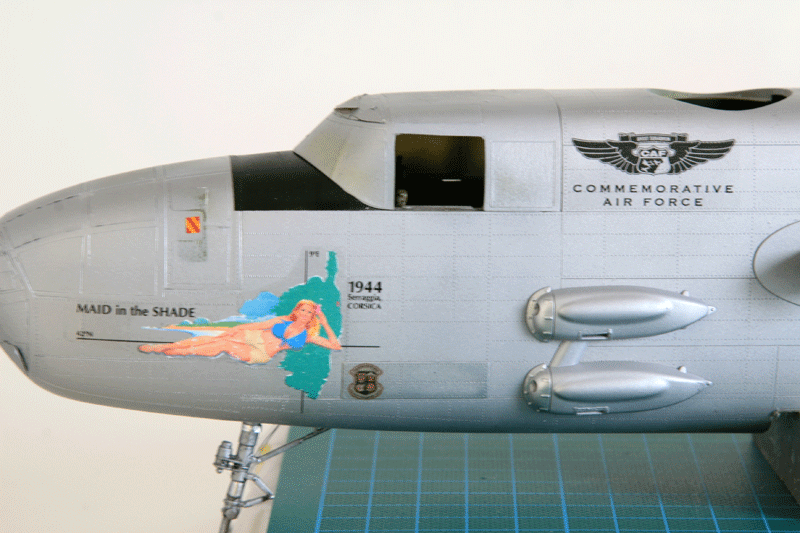
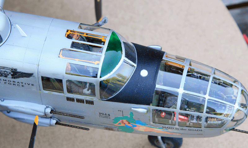
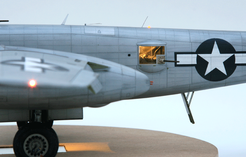
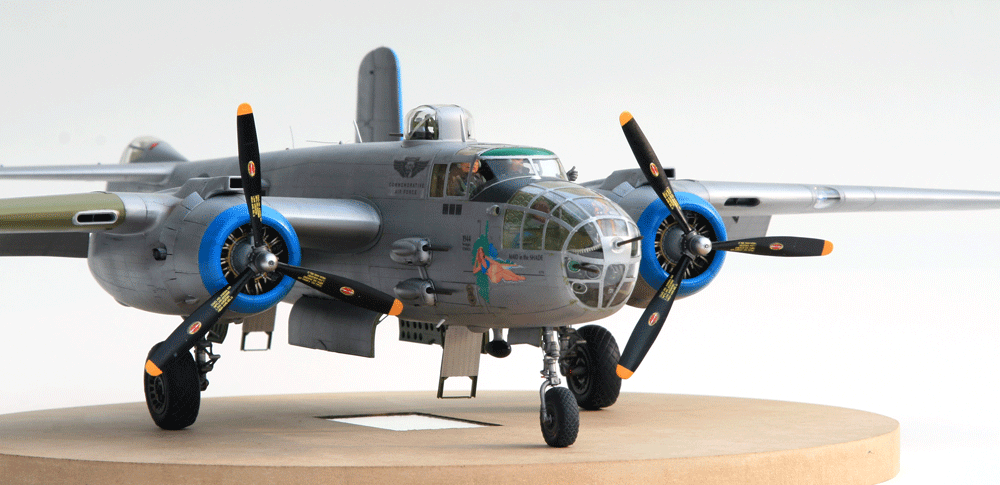
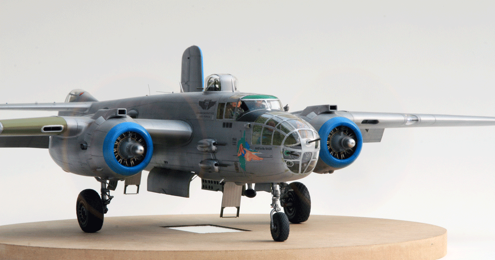
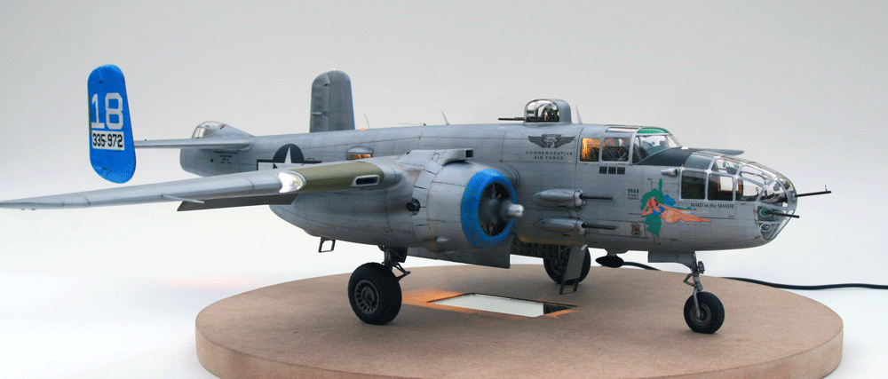
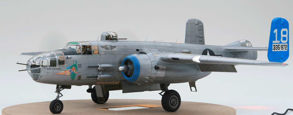
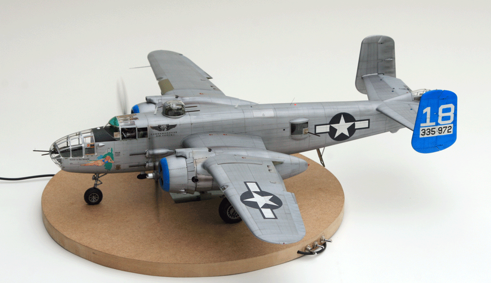
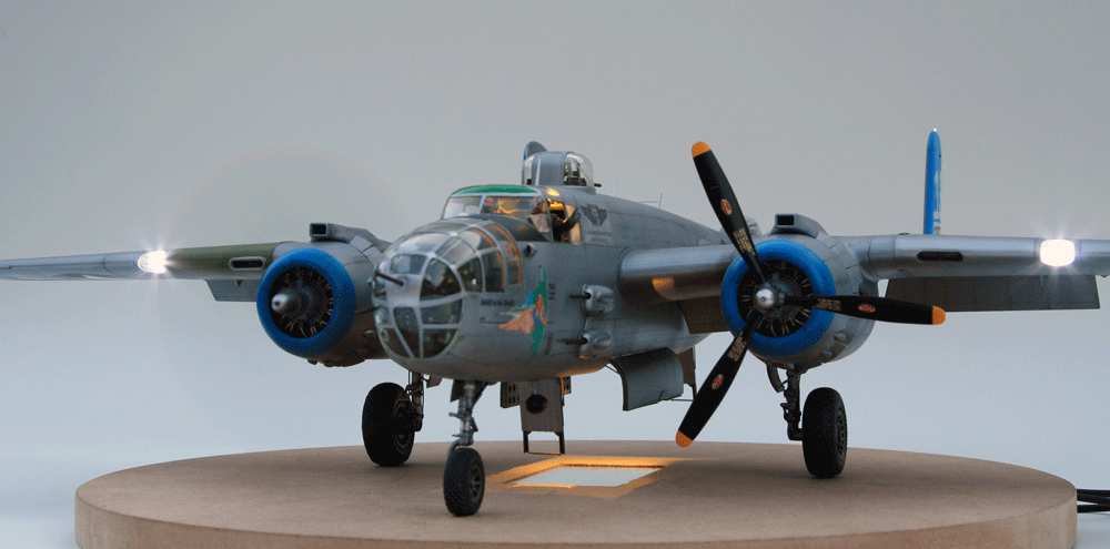
Restored B-25J Maid in the Shade 1/32
Hello gents,
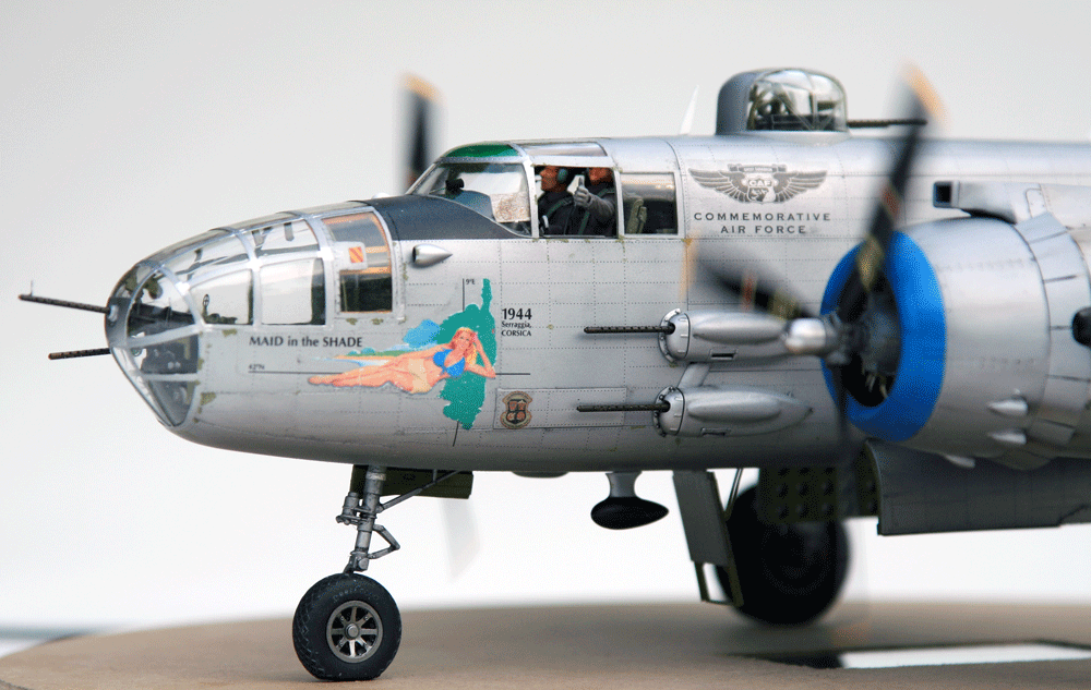
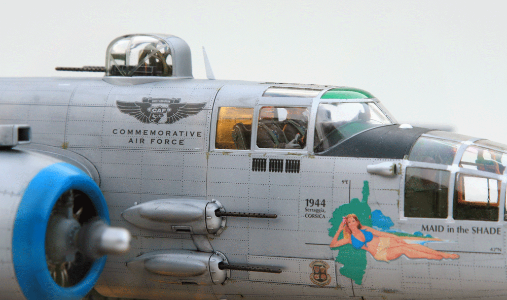
Here i am again with Something i looked forward to for a long while: a HK B-25J model.
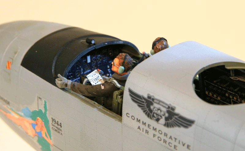
The B-25 will be the Maid in the Shade currently part of the Commemorative air force in Arizona.

The build will create a few challenges:
I broke a few teeth on that one. I think (but I may have screwed it) that Eduard instruction sheets (32-756) have some mix ups about the access doors and the inner walls to the access doors.
There is a narrow and wide door and if you follow the instructions the inner wall details PE fret won't fit the kit's parts. As they are too wide or too narrow to fit the entrance.
All it takes is switching a few parts around to fix it.
Here's how I did in the end:
1. Eduard instruction says: front door inner wall is 59-58 but should be 60-56 and inversely for the rear door on instructions
2. Eduard instruction says: front door is 69-67-66-23-22-74-53 but should be 69-67-66-23-22-[b]73-46[/b]
3. Your instruction says: rear door is 70-68-62-23-22-73-46 but should be 69-67-66-23-22-74-53
Again, that is how it was for me. I'm still scratching my head about this one wondering if I screwed up :)
The PE seats are gorgeous. Unfortunately I can't use them as I need the standard seats and certainly not the smaller co-pilot seat. So I would need to buy an extra seat PE set to get a second pilot seat or live with the kit's seats which are perfect for the restored civilian version but quite less gorgeous than the PE's, which is what I'll do.
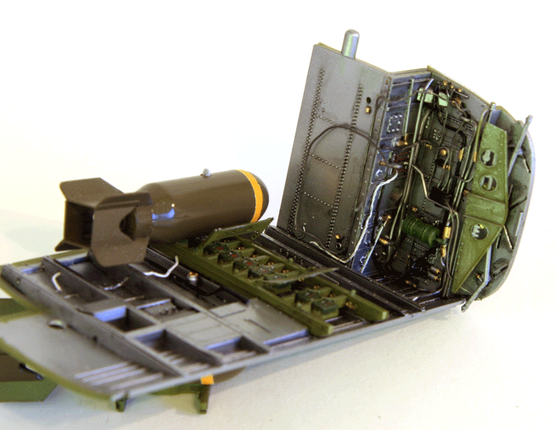
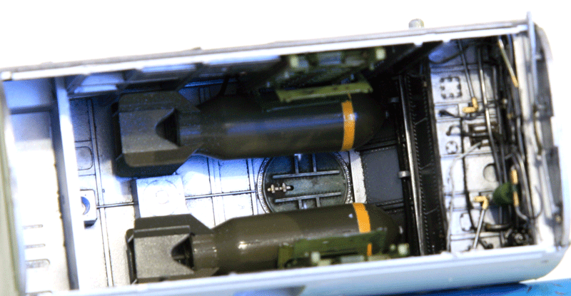
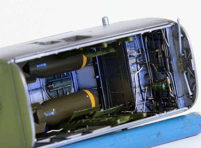
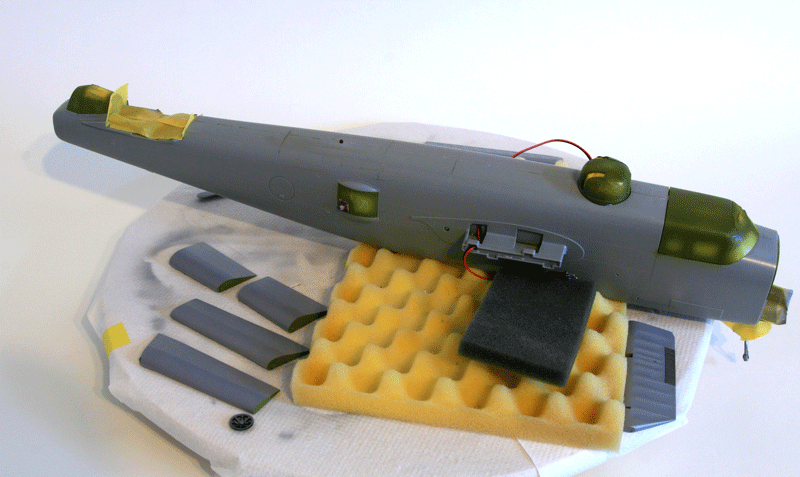
The bomb bay was painted in aluminum with details in interior green. More plumbing will be added as I close the bomb bay.
I decided to stick the two top bombs in there just to populate a bit the bay. Obviously these would be dummies :)
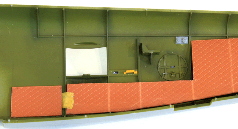
I sourced some textured plastic sheet to simulate the soundproof padding some civilian B-25 have on the inner fuselage walls. That's a great opportunity also to hide the lack of details in some part of the fuselage. The emergency exit door is not detailed inside the fuselage so I used the PE meant for the fuselage side bomb bay exit which is totally invisible after the fuselage is closed. It will be barely more visible on the fuselage side but it greatly populates that area.
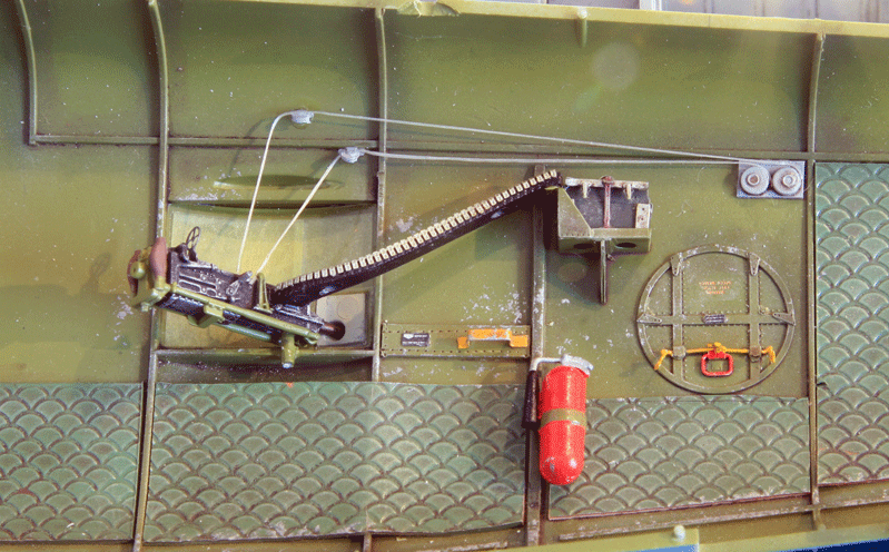
I'll also detail the counterweight mechanism for the waist guns.
Some more paint and more goodies added. The other side received the same treatment
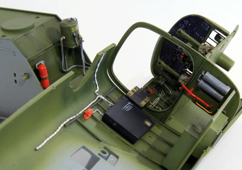
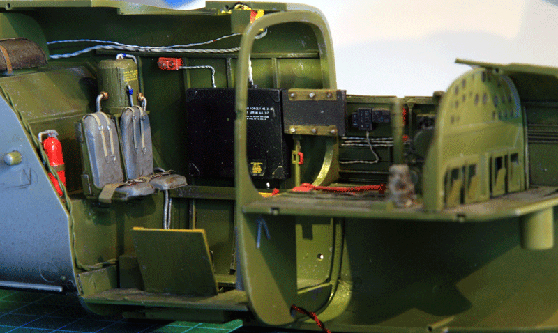
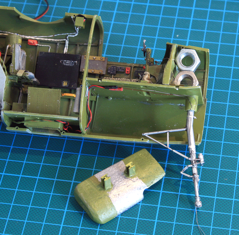
The front cabin was also painted and detailed a bit more.
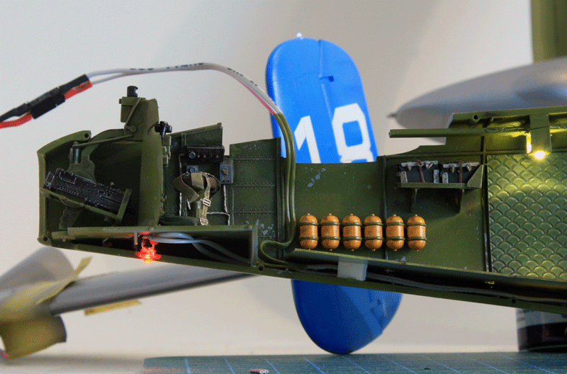
Black boxes, fire extinguishers, wires, first aid kits...
An hydraulic tank was added on the bomb bay front wall in the top turret compartment.
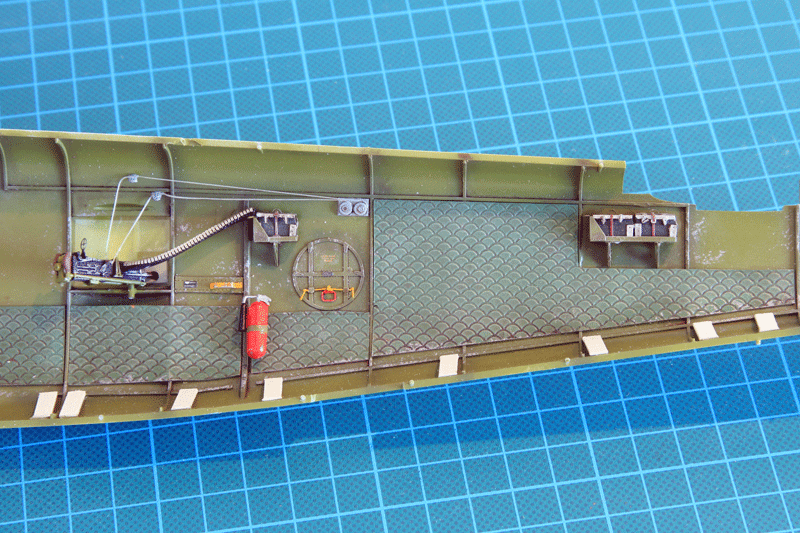
I'll add some floor in the rear compartment. If it is not done and the rear access door is left open, the internal side wall of the door are just sticking out of nowhere. The plasticard floor will address that issue.
Thank you for the video Tom. It's one of the great things about this (very slow) build. Usually I hunt down pictures on the web but on this one I realized that if you look carefully at YouTube videos you find lots of interesting details for the interior of maid in the shade :)
A few weeks ago I visited the IPMS Belgium annual contest and I met a very enthusiast guy who sells electronic components to light up our models. Here is their website.
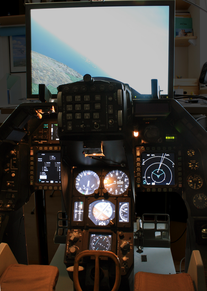
I'm a flight Sim user and along the way I build my real size 1/1 F-16 cockpit which is full of electronics as well.
 So I thought why not try to merge the two hobbies and put some electronics in that B-25.
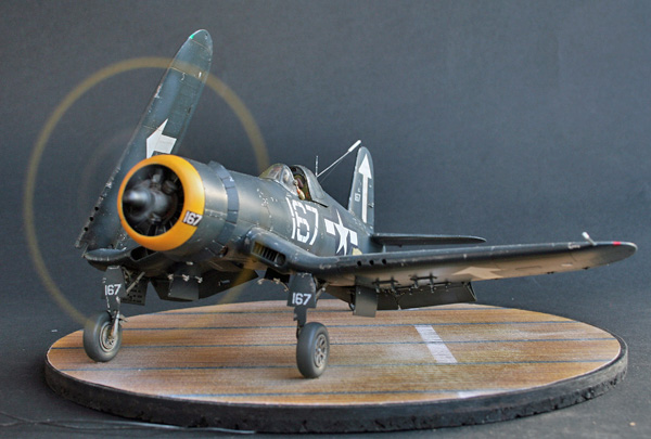
It's not the first time I'm putting some leds or motor for props. The latest I did was a F4U-1D folding it's wing:
The build had to be stopped and thought over because obviously the challenge became more complicated and as I didn't want to make too many concessions to the electrical system.
I needed to carefully plan the next steps to ensure a seamless integration of the electronics into the model.
Putting leds is really not a problem and you don't really electronics boards to do that but this guy were selling a nice and easy to use PCB that allows 8 channels for lights settable to different phases & frequency flashing.
He also has different sized engines motors that are really suitable for props - although they turn a bit fast.
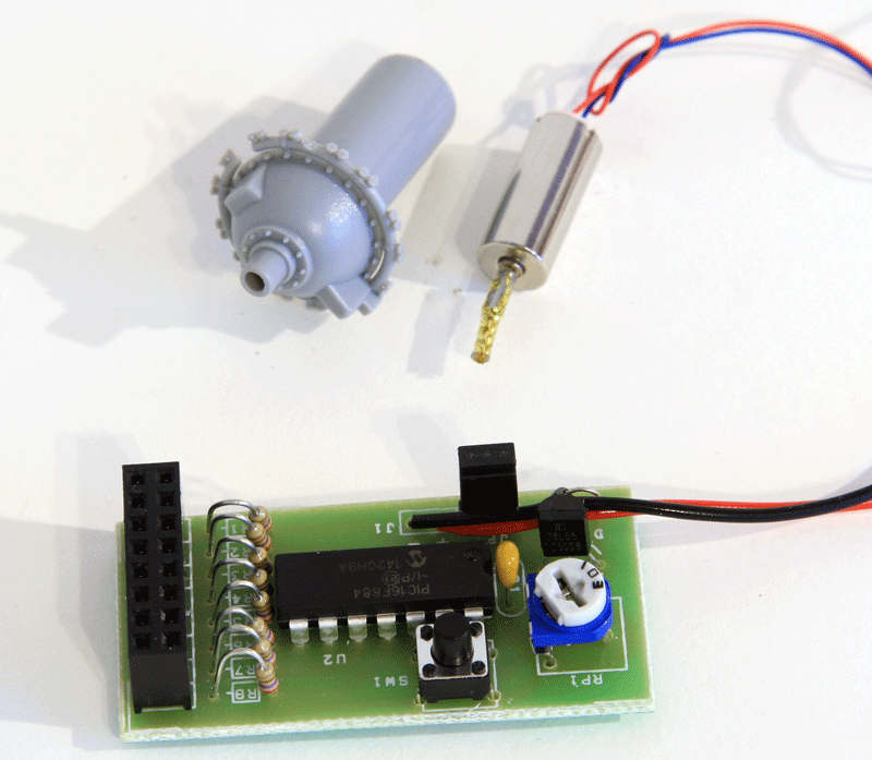
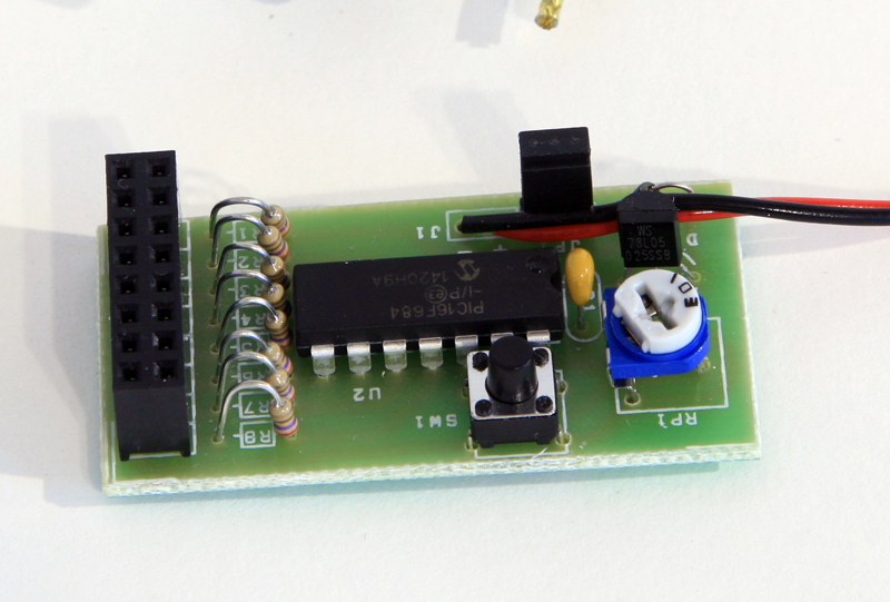
The Printed Circuit board has 8 channel output on which more than 1 led can be connected. A jumper to switch it on/off, a button to switch different flashing options for the channels and a pot to vary to frequency of each flash program.
I think there are about 16 programs predefined but I only need one.
My plan is to use 4-5 steady leds on 2 channels to light up the internal compartment, 1 channel with two leds for the left wing (Landing light and wingtip light, both steady). The same configuration for the right wing and a flashing channels for the AC lights:
One on top of the fuselage above the waist station. One below the tail (opposite phase) and the last one on the left tail.
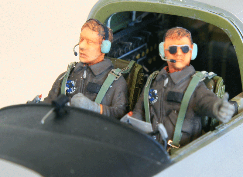
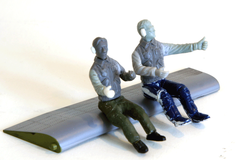
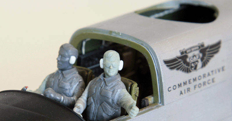
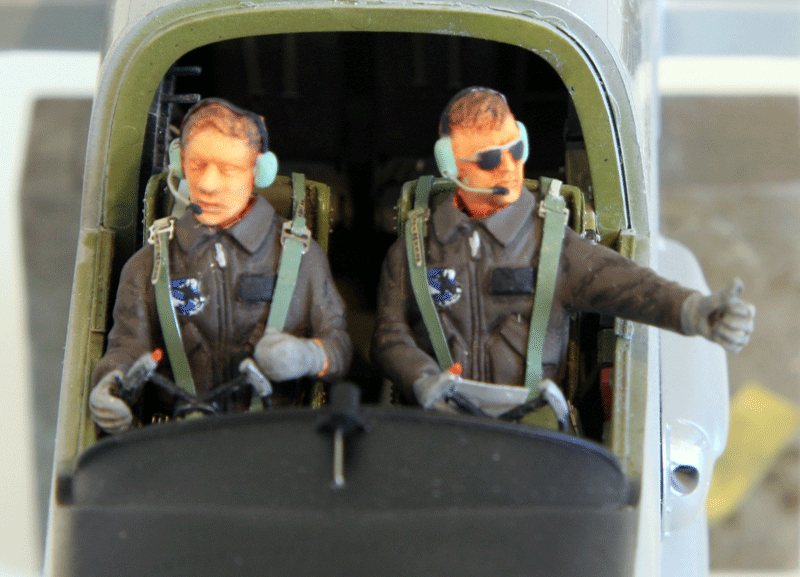
Of course with all the lights on, the engines need to turn and pilots need to be in the cockpit - finding adequate seating civilian pilots with David Clark headset is the real challenge now :)
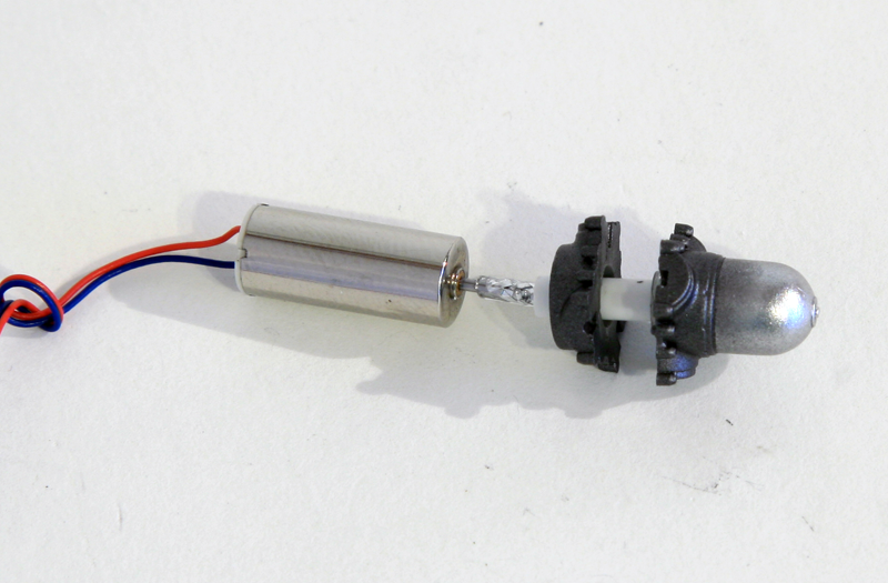
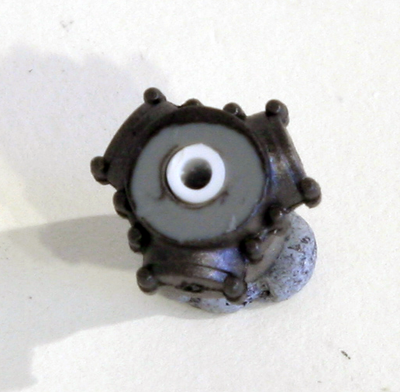
The smashing discovery is that one of the engine model Richard was selling is tailor made for the HK B-25!!
The kit part has a hollow cylinder behind the crank case in which the small engine is fitting perfectly. I couldn't believe it.
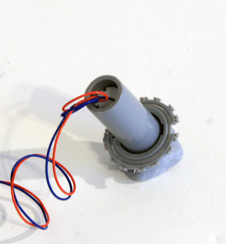
Look at that fit !! I planned to use AMS crank cases but having such a nice fit and ease of installation will force me to compromise and use the kit's part rather than the better AMS resin part.
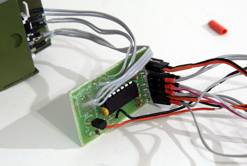 The next thing to do was to find a suitable place for the PCB inside the B-25. I considered under the (homemade) floor of the waist gun compartment and the top of the bomb bay. Top of the bomb bay was more appealing as it was better hidden and more central. But the connector were a bit high for a good fit. So I started by removing the black female connectors and replaced them with white male connectors That will make the whole assembly shorter and hopefully I could fit them on top of the bomb bay.
I also wanted to keep the button and the pot to set the programs and the flashing frequency. So I unsoldered both of them and soldered them to wires rather than straight on the PCB. The next logical thing was to find a suitable hidden place for both component:
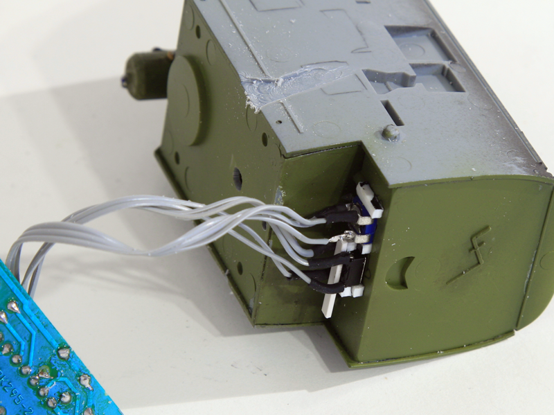
The bomb bay once again provided the obvious answer. The rear part of the Bomb bay where HK has a PE plate installed provided a flat surface big enough for both the electronic parts. Holes were made and the components attached in place on the outside walls of the bomb bay.
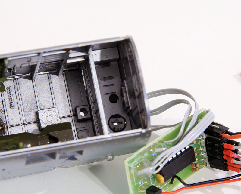
Now whatever happens I can access the PCB programs option with a small screwdriver in the bomb bay. I also shorted the jumper so the system is always ON and it can't be turned off accidentally. I wanted to avoid that as I wouldn't be able to access the PCB once the fuselage is closed.
I will rather place a switch on the main wires later on.
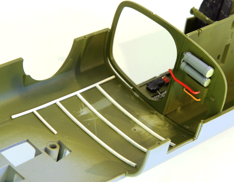
There is a light bulb in the bomb bay, one of the internal light led will go in there as well. The front compartment behind the cockpit and the nose section will have their own led as well. The rear compartment will get two leds. I built a rail to support the wires and the led that will be glued in place on top of the compartment. The rail will also hide the wires for the top red anti collision lights that will be placed on top of the waist station.
 The left tail has what I guess is a light as well, but I wasn't able to confirm that yet. Anyway, it's been placed inside the left tail as well and is ready.It's already masked with maskol for the first paint tests
Putting electronics into a plastic model is challenging and a real danger for the build completion. The chances of getting tired of the problems and sending the unfinished kit to the infamous shelf of doom are higher than with a normal kit. Luckily the electronics in this case are rather easy thanks to MagicScaleModeling who designed the board.
They designed it on the principles that modelers are experienced with glue, mastic and sanding paper and more often than not housecleaning products :) but not especially with a soldering iron.
So they offer the PCB with all the goodies you need for your project with a minimum of hassle.
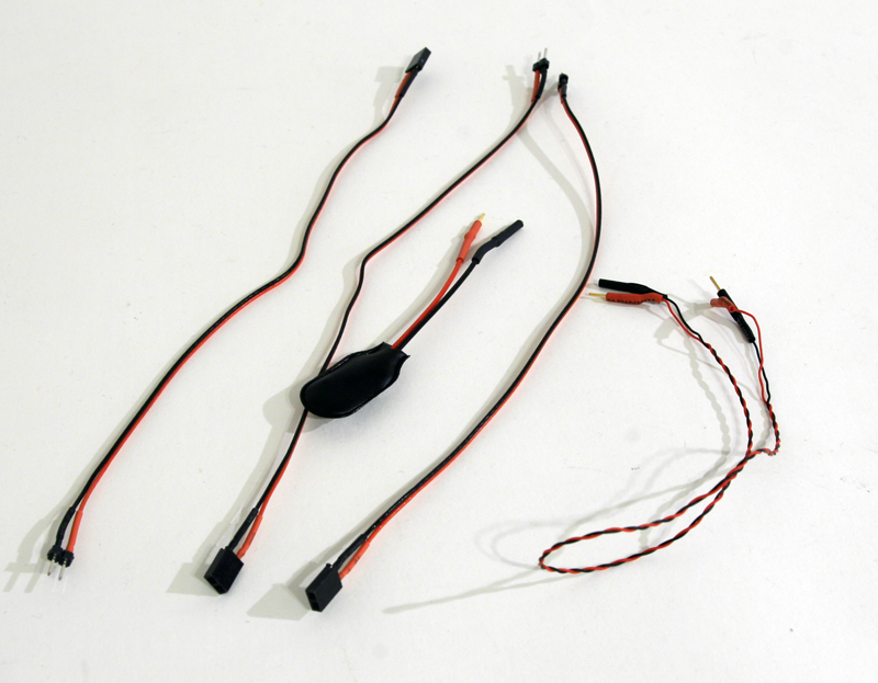
- The wires with male and female connectors soldered at variable length, the 9V power supply or the battery connector. All provided with quick foolproof connectors:
 You can't have it simpler than that. When connecting two engines, you can put them on the same battery. Rotation direction can be set by inverting polarity. So ensure you check in which direction the prop spins.
IMHO there are only two basic knowledge's you'll need to know to add electronics in your models.
So managing the electronic is very simple. What is a bit more complicated is to ensure that the electronic parts are as hidden as possible in the model.
Electronics components are huge in our scale - even 1/32, cables are way too thick to be left visible, leds might be too bright and too big as well.
the most challenging to me at least is the hide the cables. A regular electronic wire (I use IDE cable from computer) is 1mm diameter. In 1/32 scale that's a cable of 3.2 cm. Way too big for cables running alongside the compartment walls.
Luckily Magic Scale modeling made me discover these tiny cables:
They are 0.1mm diameter red and black and insulated! That means you can twist them together and use them as we would use copper wires to add wiring to our models, no risk of electronic short.
To solder them to leds you need to heat the wire first to melt the insulation. Then it solders like any other wire. They are perfect for our applications.
That's what I use when I can't make the cables invisible.
In some cases hiding the leds will require creativity. To light up the rear compartment I created a rail in plasticard. The rail is not in the real B-25 but that's an artistic licence I took to solve one of the problem.
Internal floodlight is perfectly made in scale with low warm white lights with short & rounded faces. They are not yellow but not too blue either. They are just perfect for flood lighting.
In other cases, it's dead easy to do:
Let's take the wing landing light of the B-25. the kit has a plastic part for the spot embedded in the wing.
I'll use a 1.8mm white led long and flat face and round the face myself with a small file until I have a nice bulb shape.
Next I'll drill 1.6mm through the transparent plastic part and force the led Inside the kit part
and light it up
All that's needed now is to solder the led and connect it to the CB in the fuselage. It's a tad bright, but landing lights are supposed to be bright. I may try to dim it a bit though...
Let's do an engine test run:
The engines are a pleasure to work on. The cylinders are painted aluminium's and given a wash of black oil. Most of the structure is painted black and slightly dry brushed in aluminum's. I also used titanium gold paint and the crank case is painted H307
I won't display any open panels so most of it will be invisible.
For that reason many of the PE parts for the engines from Eduard Big Ed kit won't be used.
The front face will get some more detailing.
As I said before I unfortunately won't use the AMS crank case because the Magic Scale Modeling motors fit to nicely the kit parts.
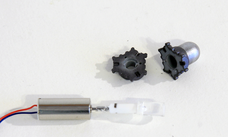
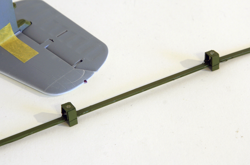
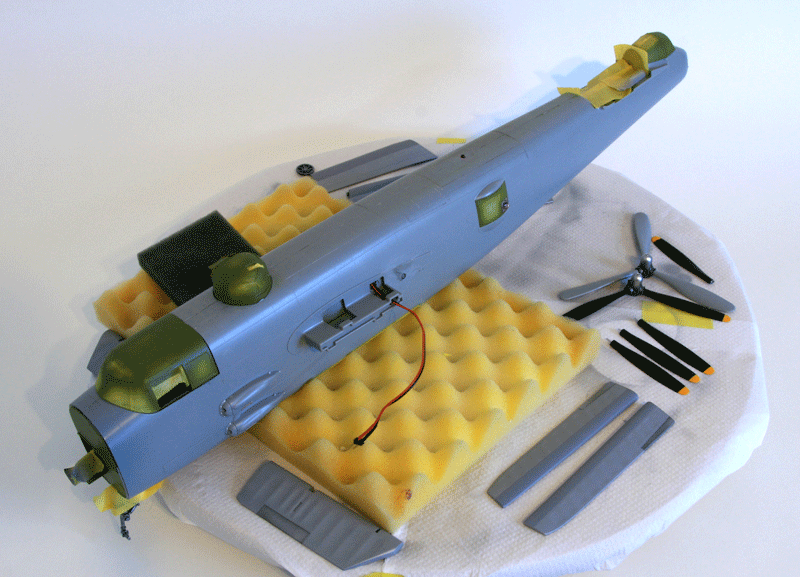
The props need some work to be used with the motor.
A transparent rod was cut to size and will be inserted into the propeller dome. The smaller white rod sits inside the transparent bigger rod.
The metal extended motor rod will go through both of them to ensure a good grip during rotation.
The white rod is cut smooth behind the prop governor. Normally the prop sits on the bit extended from the crank case but the fit is too tight and I am concerned it would prevent the props to turn freely and burn the motor. So I will cut the kit's crank case smooth to prevent that.
The motor sits inside the engine and the rod has been extended a bit with 1mm metal rod.
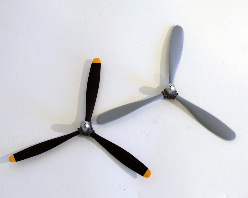
Kit's props are quite fat compared to the nice AMS resin replacement. The only advantages of the kit's part is that they sit perfectly well in he governor with the specific shaped holes.
AMS replacement pins are too thick. I'll cut them and replace them with small metal rods.
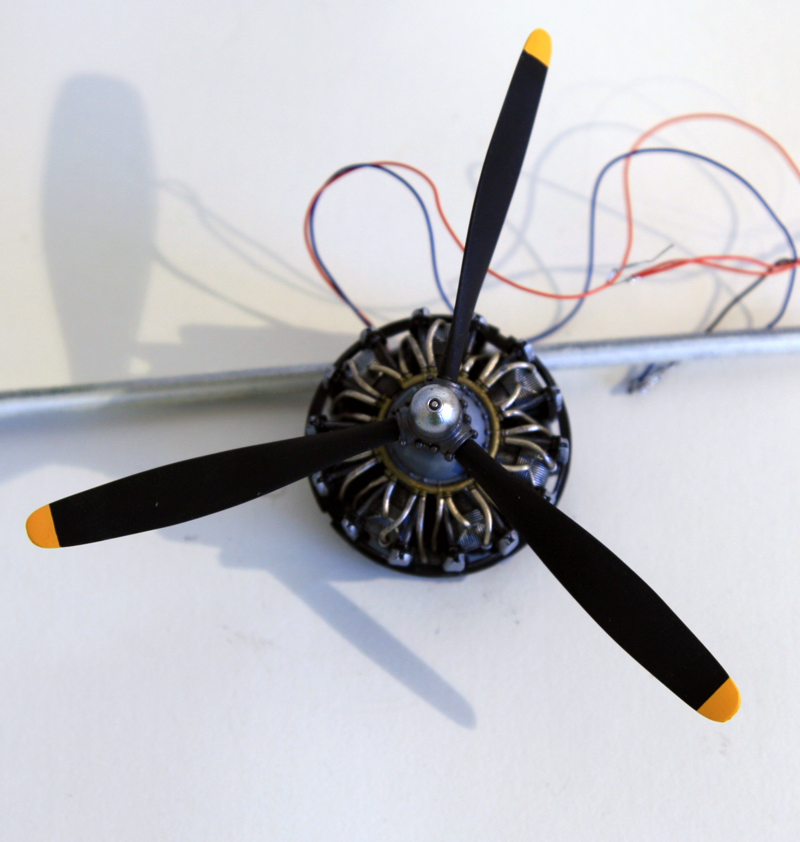
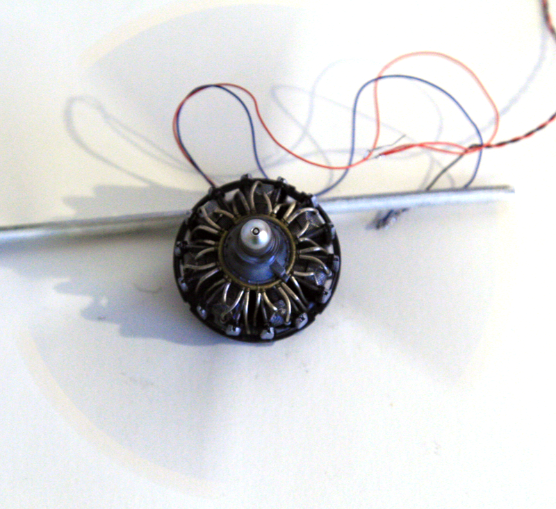
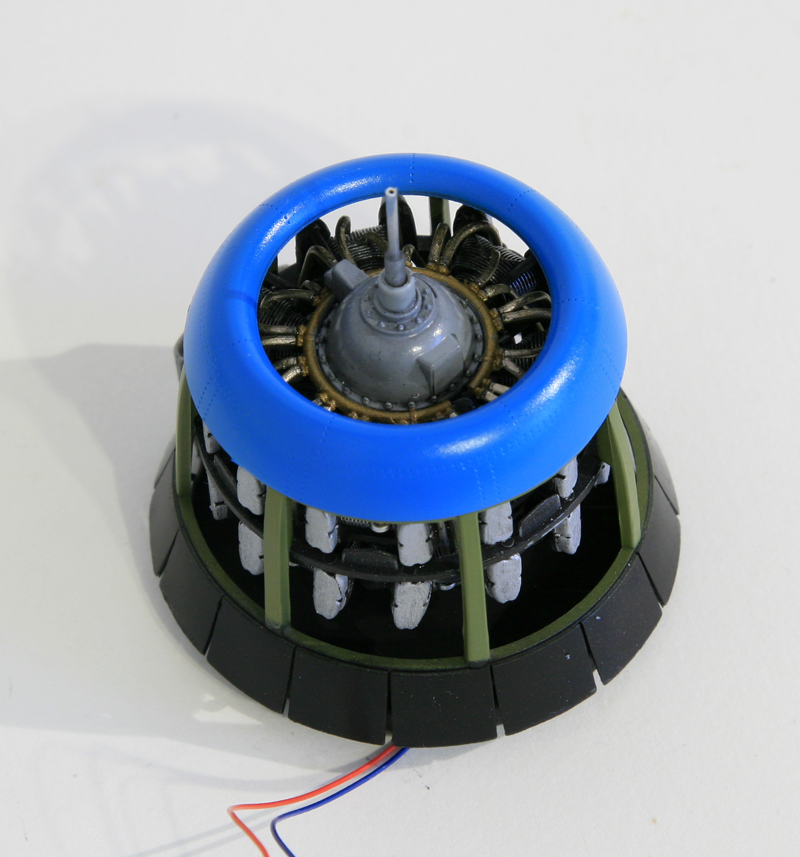
And the motor is turned On. It turns with a minimum of vibrations. Concept is validated and I can move on.
It's now about time we get some paint on that model and get back to old fashioned modelism :)
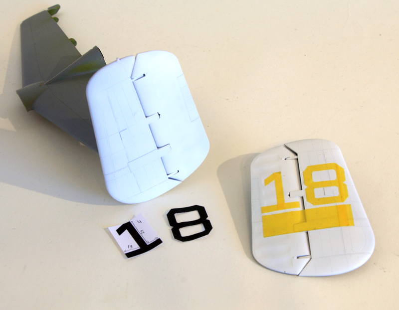
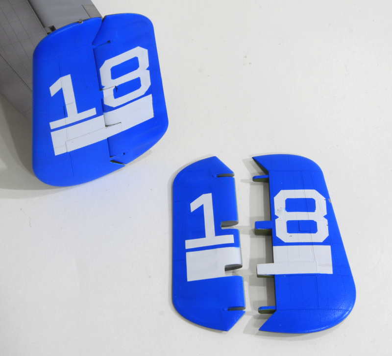
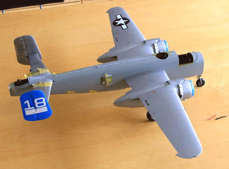
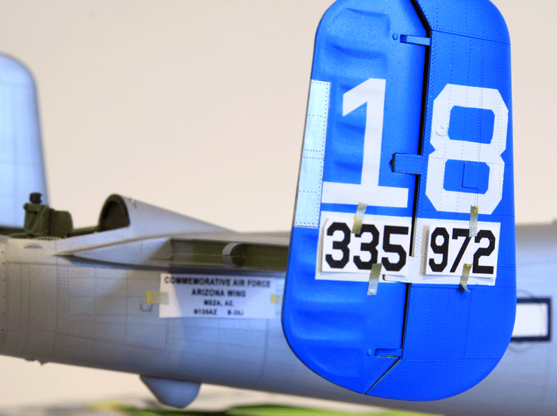
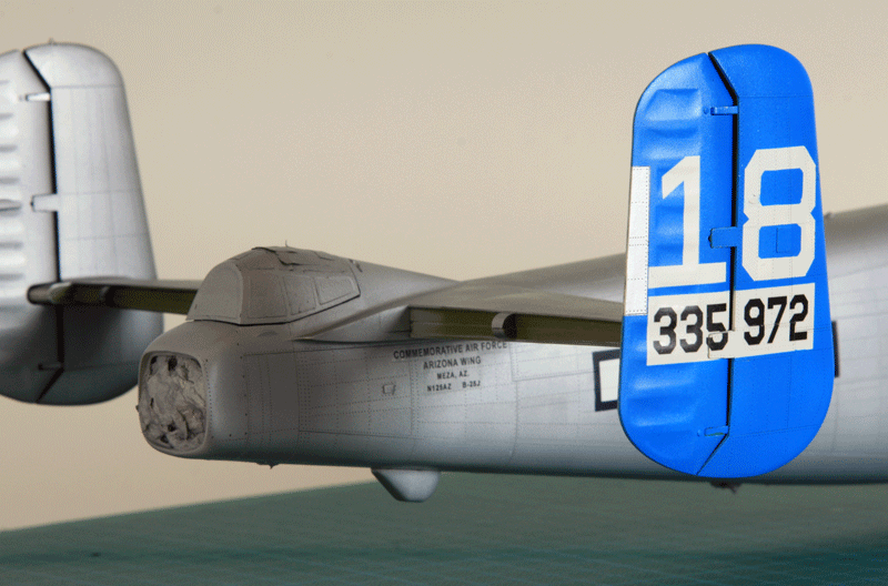
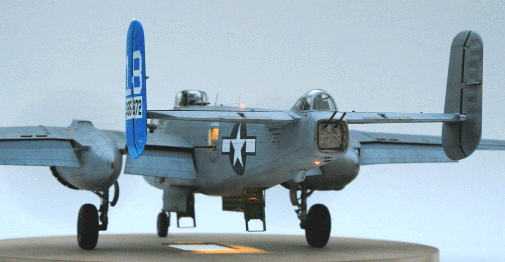
First the tails. Since I will do most of my decals i will spare me the trouble for the big ones and paint them straight on the model.
The easiest will be the big 18 number on both tails:
I started painting the tail in white, then masked the numbers and the white rectangle for the decal serials and then sprayed blue
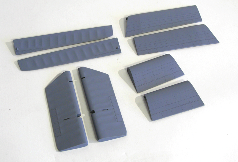
Next was to try out some alclad tones on the model. Unlike some civilian restored B-25 Maid in the shade isn't very shiny. Matter of fact it's pretty dull.
I first tried airframe aluminum's thinking it was less shiny than aluminum's but soon realized that it is shinier and darker than aluminum's. not good for this project.
I then tried semi mate aluminum's and that was about the colour I wanted to have.
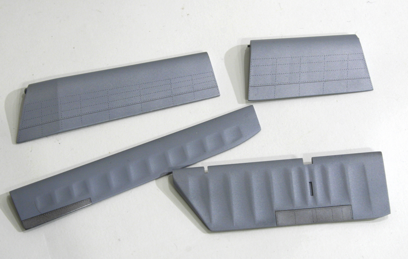
To illustrate the fabric on the movable controls I tried dull aluminum's which gives a very good difference from the metal of the airframe and painted the trim tabs in aluminum's to make them stand out the dull fabric colour.
The good thing about these non bright colours from alclad is that I can spray them over a coat of Mr Surfacer which for me is way easier than a gloss black should I have chosen aluminum's or airframe aluminum's.
Here are the test parts primed with Mr Surfacer:
and painted in the alclad colours referenced above:
Once they are all assembled on the tail unit, the nuances stand out pretty well:
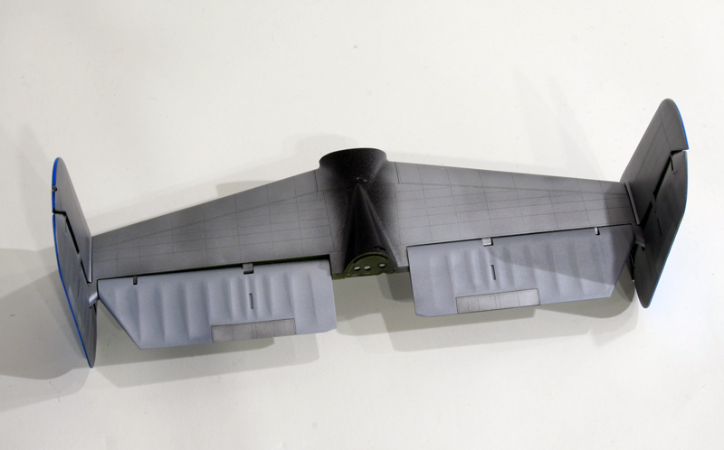
The dark picture don't do them justice - It's hard to get good lights in this time of the year
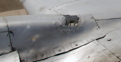
The carb intake challenge:
I knew right from the start that converting the engines exhausts and carburetor intake was going to be a huge challenge. After studying a lot of pictures adapted to scale, I calculated the front intake to be 8x5mm
I used a perfectly aligned picture of a B-25 engine and scaled it to the kit's parts. printed it and put the kit's parts on top of it. Then simply measured the rectangular shape:
For the side of the intake, I tried to find again a perfectly aligned picture of the side view, scaled it to the kit's part and print.
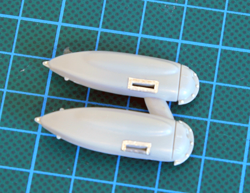
The engine pods are undergoing surgical modifications:
First the Clayton exhausts were removed accordingly from the engine panels. The plastic was simply cut away from the parts. A plastic sheet was glued on the internal wall of the panel and the hole was then filled with Tamiya light curing putty. Once dry and sanded flat, I added Vallejo white putty and sanded again. Checked my work with a coat of Mr Surfacer and applied super glue on the holes remaining. Sanded flat again before the glue was completely cured.
One of the two hole is very close to the panel edge so it is very fragile. I broke two out of four panels at that tiny junction point. It's almost impossible to repair on the panel, but it will be very easily repaired once the panels are on the engine cowls, so I left that for later.
 Parts 3, 5 and 7 were left untouched. One Clayton exhaust from part 4 was removed (the upper one) and both Clayton exhaust were removed from part 1, 2 and 6.
Accordingly, only the relevant internal exhaust ducts were glued to the cylinders (15, 22,16,10, 17 and 11)
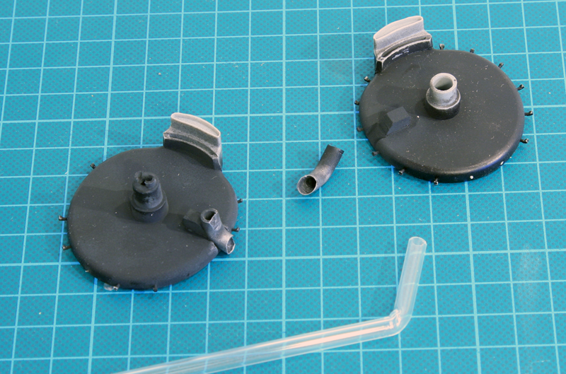
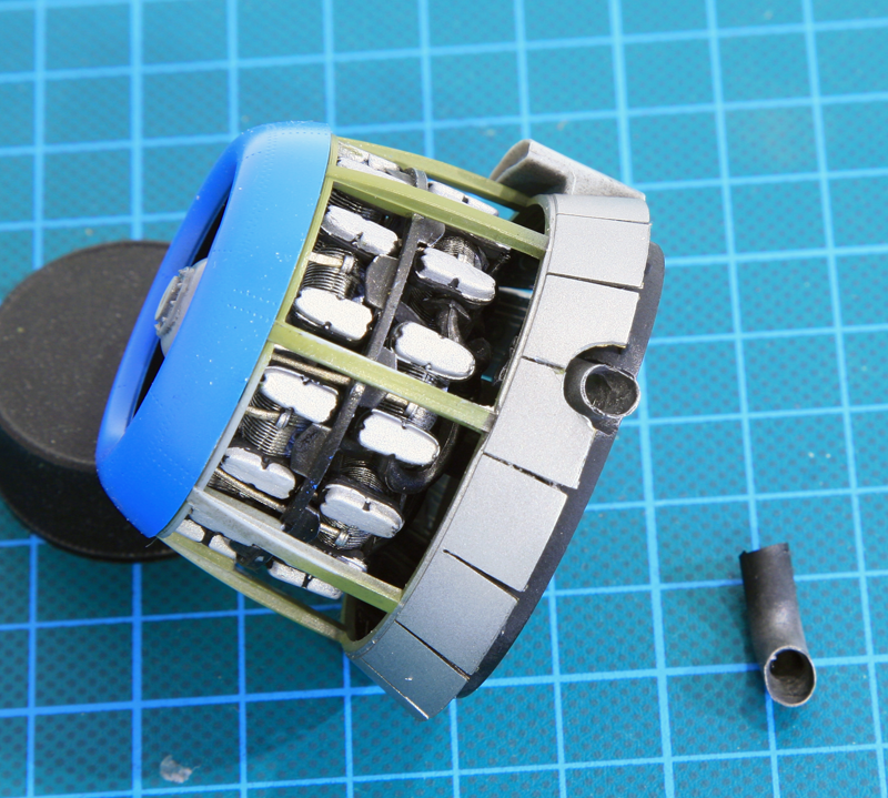
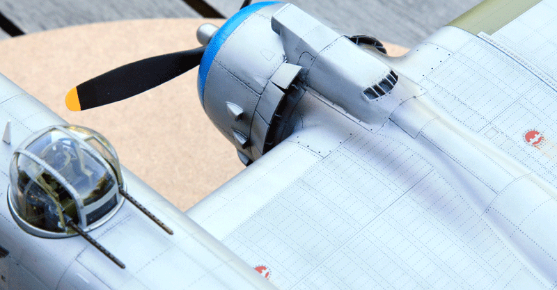
The new exhaust collector that goes outboard the engine has been shaped by lightly heating a transparent plastic rod to about an angle of 80° then cut to shape. The outer wall thinned with the dremel.
To place it at the relevant spot a bit of angled sanding is required on the cowl flaps support plate and the exhaust is maintained in place with an extra angled support on the engine rear face.
Obviously two cowl flaps have been cut to let the exhaust pass through.
the exhaust will be weathered later on as the whole assembly still need to be primed and painted
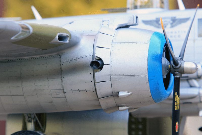
The new carburetor intake has been built with 1mm plasticard to create a 8x5mm rectangle.
The intake lip has been sanded round.
The original intake has been cut to place the new one just for positioning purposes. Once happy with the result, I will further cut the old intake remaining sides and shape the new intake with milliput.
The biggest challenge is the rear openings. I wanted to milliput the whole part but if I do that I will have lots of trouble making that part, so I decided to make a structure in plasticard first and milliput around the structure.
Here are the attempts at the rear structure of the carburetor intake:
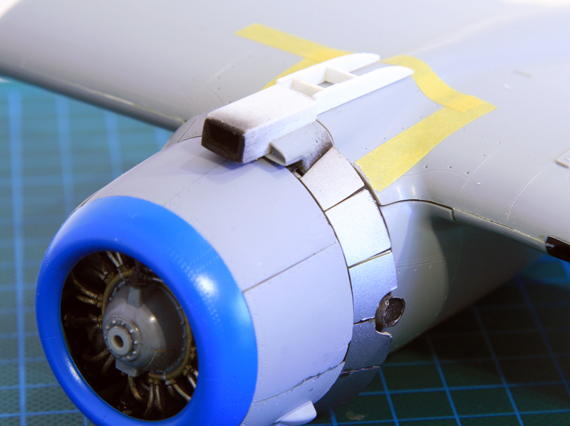
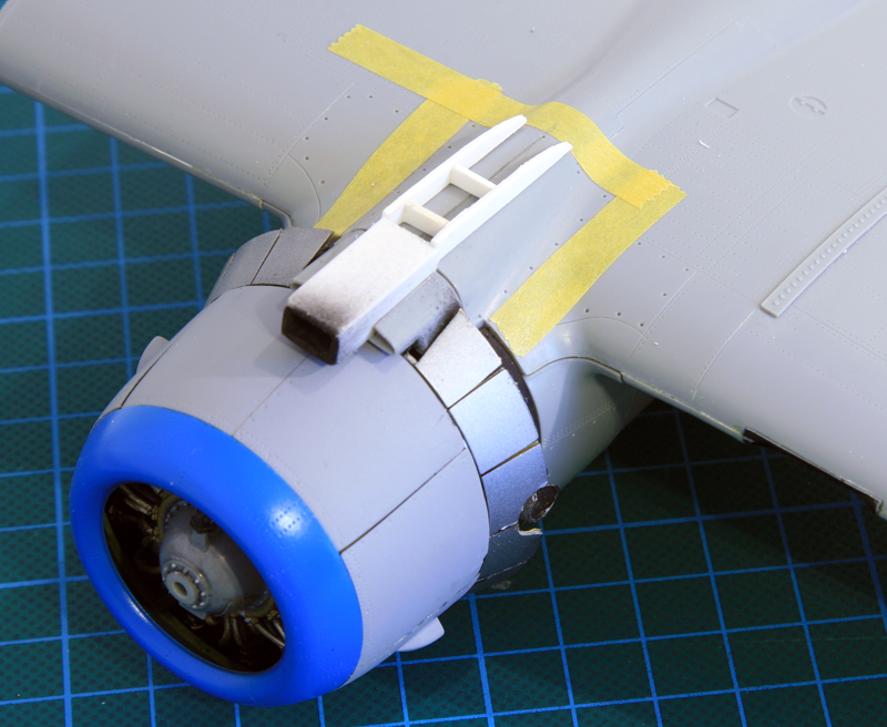
I'll now try to shape that specific part:
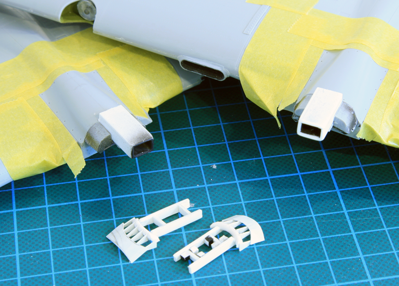
I first made the shape of the rear vents (?) with bits of plastics
To avoid having to build to whole engine nacelles before shaping the new carburetor intake I cut the top of the engine rear face supporting the cowl flaps so I could glue that bit on the top of the wing.
That way I can build the nacelle, engine and gear later on and probably avoid breaking the whole assembly as I shape and sand the carburetor parts.
I protected the wing with masking tape as my milliput work is usually messy :)
Once happy with the positioning I glued all scratched part to the top wings and started milliputting the new shape around the plasticard structure.
The milliput was smoothed with water to be as shaped and as smooth as possible
And then coarse sanded before removing the mask. Next step is to sand with finer grit and get it smooth.
I know it's far from the perfect shape. I took some shortcuts to make my life easier like having the rear part horizontal up to the vents where normally they should be angled down already. But I couldn't find an easy way to make that down slope.

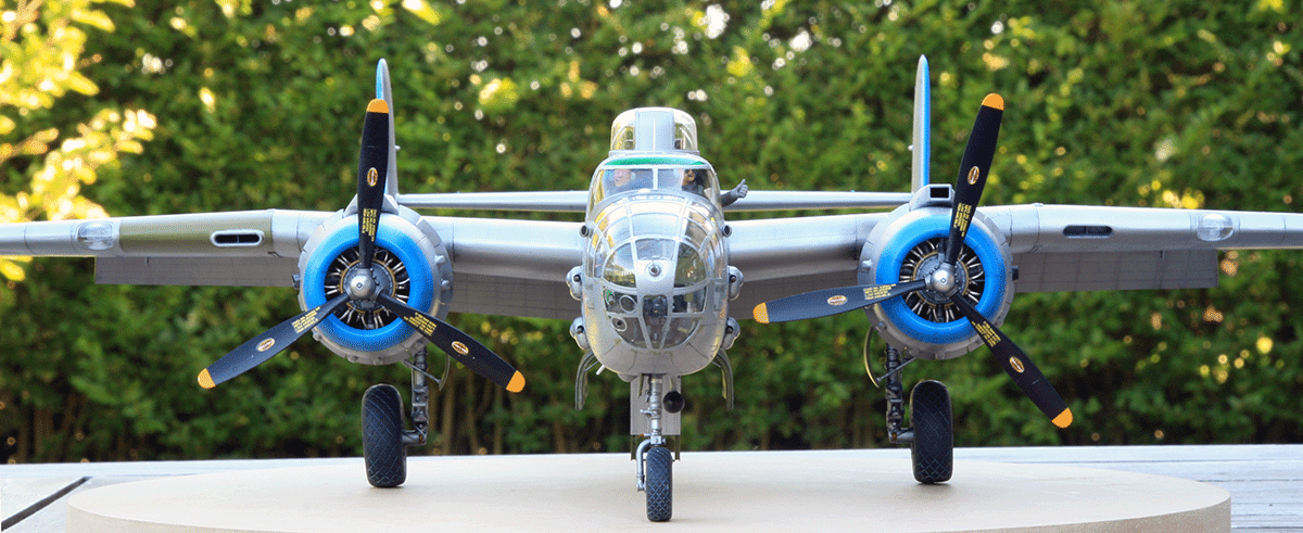
 Engines ON
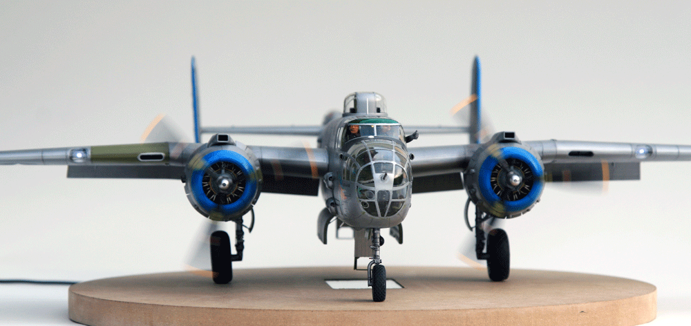
 The separate switches for the engines allow to have different starting engine configurations
Here i am again with Something i looked forward to for a long while: a HK B-25J model.
The B-25 will be the Maid in the Shade currently part of the Commemorative air force in Arizona.
The build will create a few challenges:
- Obviously the interior has been adapted to air rides rather than combat. Although the guns are still installed there are lots of seats all over the forward and aft cabin. I'm not sure I'll be able to make the internals as the modern restored aircraft, especially considering that most of all this will be invisible once assembled.
- The natural metal finish will be interesting as well and of course there is no decal for this one - well not that i know of. So i had to design my own. the larger decals (national insignias and tail numbers will be painted with masks as illustrated in the other blogs articles.
The decals are not final yet, just a work in progress when I need a break from the bench.
- The biggest issue for me will be the need to convert the engine exhaust from the full Clayton of the model to the modified Clayton that restored B-25 usually have. Some of the top cowling individual exhausts are collected into one larger side exhaust pipe and the carburetor intake on top of the wing is much larger and rectangular in shape.
- The model will use a bit of aftermarket products such as the usual Eduard PE sheets, AMS props, Brassin wheels, brass gears and turned barrels for the .50s. Not forgetting the much needed nose weight.
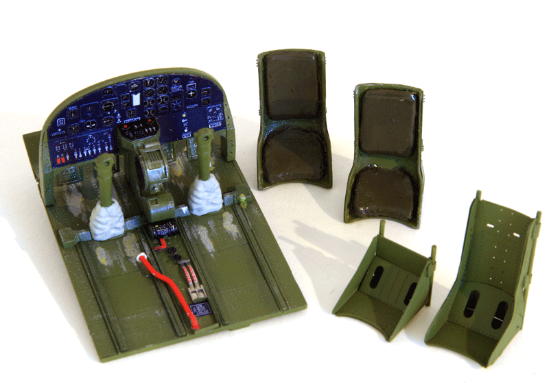
Let's start with the internal work and some PE fun with the Eduard sheets for the B-25J:
bomb bay
Cockpit
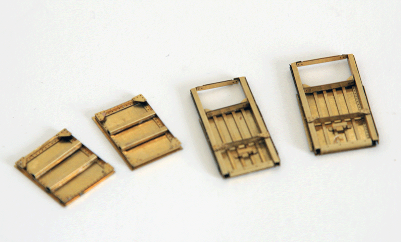
Access doors
There is a narrow and wide door and if you follow the instructions the inner wall details PE fret won't fit the kit's parts. As they are too wide or too narrow to fit the entrance.
All it takes is switching a few parts around to fix it.
Here's how I did in the end:
1. Eduard instruction says: front door inner wall is 59-58 but should be 60-56 and inversely for the rear door on instructions
2. Eduard instruction says: front door is 69-67-66-23-22-74-53 but should be 69-67-66-23-22-[b]73-46[/b]
3. Your instruction says: rear door is 70-68-62-23-22-73-46 but should be 69-67-66-23-22-74-53
Again, that is how it was for me. I'm still scratching my head about this one wondering if I screwed up :)
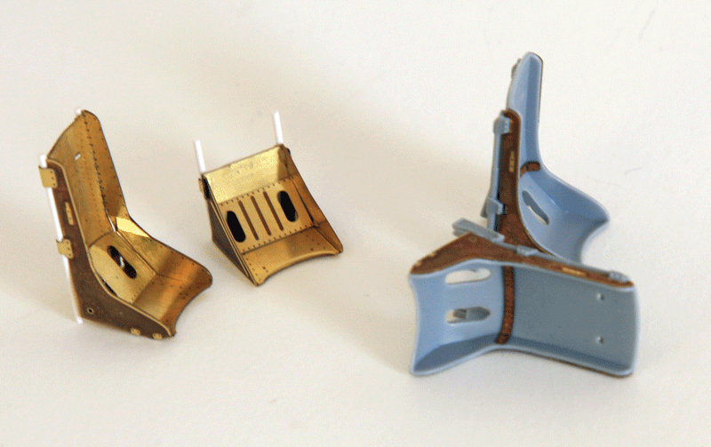
Seats
The crew of Maid in shade certainly earned the right to get comfortable flying the B-25 so I added some cushion in milliput on the kit's seats
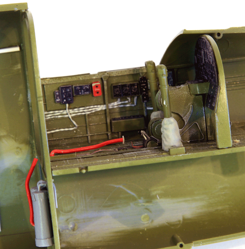
The hydraulic pump was redone with soldering wire - although I screwed up the end of it. the rest is basic painting, and Eduard PE's. weathering is WIP.
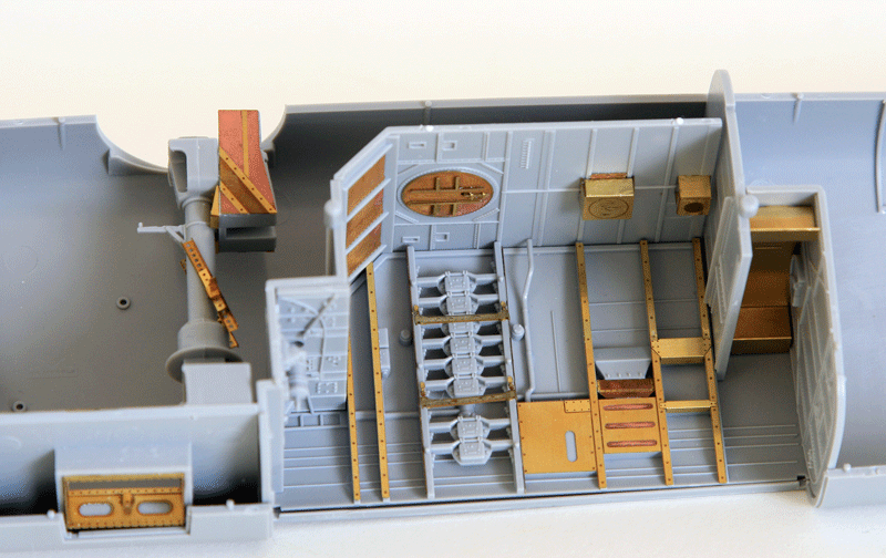
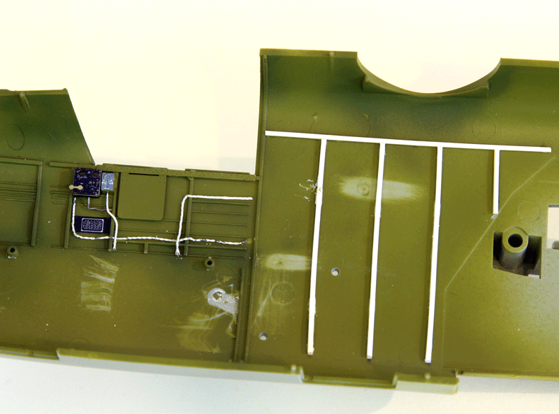
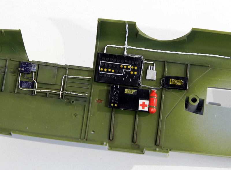
Right side wall populated with Eduard PE. I added some wires for the boxes.
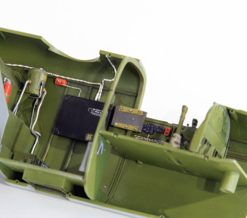
I also added some basic detailing in the top turret compartment behind the cockpit. The gear manual pump and some tanks.
There is no wall detail at all in the top turret compartment, I'm not going to remake the whole structure but I added some very basics ones so it looks at least like the rear compartment. That area will be heavily populated anyway with large boxes.
Maid in the Shade don't have the turret column installed and the turret is fixed in the rear position. so I will leave that out of the compartment.
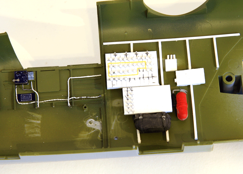
Populating the top turret compartment:
The other side
Some work on the rear with Eduard stuff:
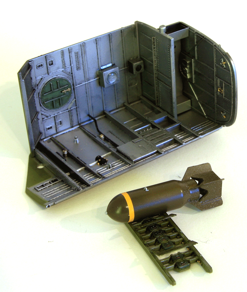
The bomb bay was painted in aluminum with details in interior green. More plumbing will be added as I close the bomb bay.
I decided to stick the two top bombs in there just to populate a bit the bay. Obviously these would be dummies :)
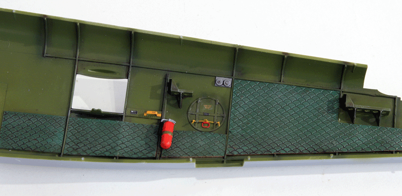
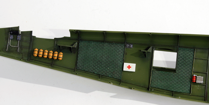
I sourced some textured plastic sheet to simulate the soundproof padding some civilian B-25 have on the inner fuselage walls. That's a great opportunity also to hide the lack of details in some part of the fuselage. The emergency exit door is not detailed inside the fuselage so I used the PE meant for the fuselage side bomb bay exit which is totally invisible after the fuselage is closed. It will be barely more visible on the fuselage side but it greatly populates that area.
I'll also detail the counterweight mechanism for the waist guns.
Some more paint and more goodies added. The other side received the same treatment
The front cabin was also painted and detailed a bit more.
Black boxes, fire extinguishers, wires, first aid kits...
An hydraulic tank was added on the bomb bay front wall in the top turret compartment.
I'll add some floor in the rear compartment. If it is not done and the rear access door is left open, the internal side wall of the door are just sticking out of nowhere. The plasticard floor will address that issue.
Thank you for the video Tom. It's one of the great things about this (very slow) build. Usually I hunt down pictures on the web but on this one I realized that if you look carefully at YouTube videos you find lots of interesting details for the interior of maid in the shade :)
A few weeks ago I visited the IPMS Belgium annual contest and I met a very enthusiast guy who sells electronic components to light up our models. Here is their website.
I'm a flight Sim user and along the way I build my real size 1/1 F-16 cockpit which is full of electronics as well.
It's not the first time I'm putting some leds or motor for props. The latest I did was a F4U-1D folding it's wing:
The build had to be stopped and thought over because obviously the challenge became more complicated and as I didn't want to make too many concessions to the electrical system.
I needed to carefully plan the next steps to ensure a seamless integration of the electronics into the model.
Putting leds is really not a problem and you don't really electronics boards to do that but this guy were selling a nice and easy to use PCB that allows 8 channels for lights settable to different phases & frequency flashing.
He also has different sized engines motors that are really suitable for props - although they turn a bit fast.
The Printed Circuit board has 8 channel output on which more than 1 led can be connected. A jumper to switch it on/off, a button to switch different flashing options for the channels and a pot to vary to frequency of each flash program.
I think there are about 16 programs predefined but I only need one.
My plan is to use 4-5 steady leds on 2 channels to light up the internal compartment, 1 channel with two leds for the left wing (Landing light and wingtip light, both steady). The same configuration for the right wing and a flashing channels for the AC lights:
One on top of the fuselage above the waist station. One below the tail (opposite phase) and the last one on the left tail.
Of course with all the lights on, the engines need to turn and pilots need to be in the cockpit - finding adequate seating civilian pilots with David Clark headset is the real challenge now :)
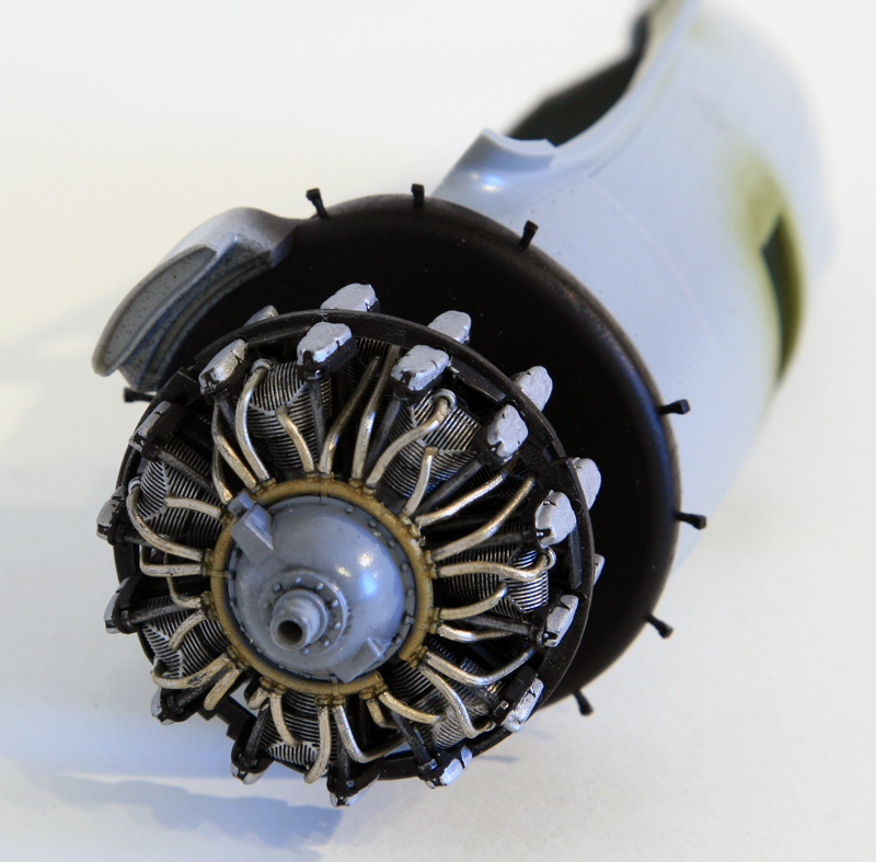
The smashing discovery is that one of the engine model Richard was selling is tailor made for the HK B-25!!
The kit part has a hollow cylinder behind the crank case in which the small engine is fitting perfectly. I couldn't believe it.
Look at that fit !! I planned to use AMS crank cases but having such a nice fit and ease of installation will force me to compromise and use the kit's part rather than the better AMS resin part.
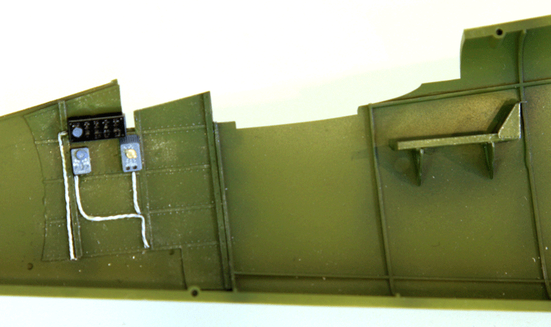
I also wanted to keep the button and the pot to set the programs and the flashing frequency. So I unsoldered both of them and soldered them to wires rather than straight on the PCB. The next logical thing was to find a suitable hidden place for both component:
The bomb bay once again provided the obvious answer. The rear part of the Bomb bay where HK has a PE plate installed provided a flat surface big enough for both the electronic parts. Holes were made and the components attached in place on the outside walls of the bomb bay.
Now whatever happens I can access the PCB programs option with a small screwdriver in the bomb bay. I also shorted the jumper so the system is always ON and it can't be turned off accidentally. I wanted to avoid that as I wouldn't be able to access the PCB once the fuselage is closed.
I will rather place a switch on the main wires later on.
There is a light bulb in the bomb bay, one of the internal light led will go in there as well. The front compartment behind the cockpit and the nose section will have their own led as well. The rear compartment will get two leds. I built a rail to support the wires and the led that will be glued in place on top of the compartment. The rail will also hide the wires for the top red anti collision lights that will be placed on top of the waist station.
Putting electronics into a plastic model is challenging and a real danger for the build completion. The chances of getting tired of the problems and sending the unfinished kit to the infamous shelf of doom are higher than with a normal kit. Luckily the electronics in this case are rather easy thanks to MagicScaleModeling who designed the board.
They designed it on the principles that modelers are experienced with glue, mastic and sanding paper and more often than not housecleaning products :) but not especially with a soldering iron.
So they offer the PCB with all the goodies you need for your project with a minimum of hassle.
- The wires with male and female connectors soldered at variable length, the 9V power supply or the battery connector. All provided with quick foolproof connectors:
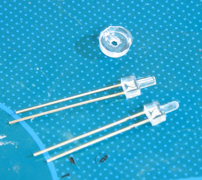
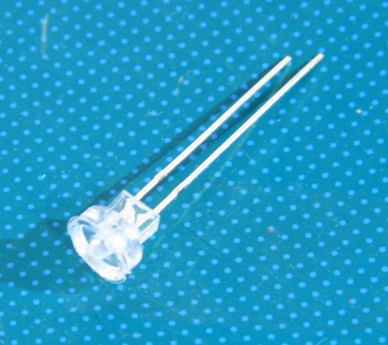
- the leds (and they have plenty different type very suitable for modeling project).
Cold white, Warm white, Coloured (although it's not ideal, more on that later) flat top, rounded top, long short, ...
All the leds are the smallest possible, the one above are less than 2 mm.
We could also use SMD (Surface Mounted Leds) which are even smaller but very bright and IMHO way too bright for the scale effect.
The long flat top leds can be sanded to any shape.
The small round top are ideal for compartment lights
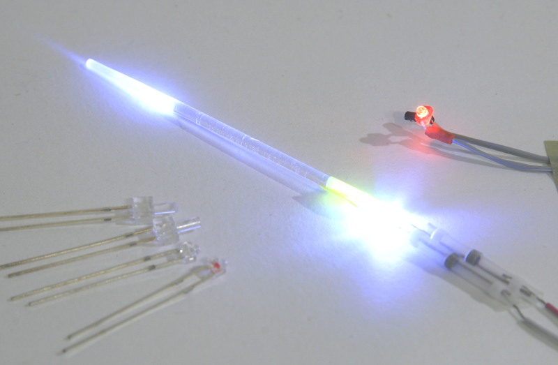
The long flat faces are ideal for optic fiber effects (more on that later)
Coloured leds have different voltage and their intensity from one colour to another is variable. So I always prefer to use all white leds (cold and warm depending of the application) and paint the leds with transparent tamiya paint myself. That way I can keep the led brightness more or less constant.
Usually leds are too bright for the scale effect, so I tend to use the fibre optic effect as illustrated in the above picture. The flat face leds are ideal for that as it's very easy to find any transparent plastic rod of about the same diameter as the led and tape it to the top of the led. As you can see on the above picture the light pass through the plastic tube but doesn't shine through unless you sand the tube. That's perfect when you want to add lights in tiny spots where the led is still too big to be inserted (like wingtips for instance).
You sand the tube to the desired shape and place the led further down in the wing where you have enough room.
Beside the fitting issue it also decrease the led brightness which is great for the scale effect. Wingtips lights aren't usually very bright and have to be toned down for the scale effect.
The innards of the plastic part might need to be painted black to offer a further opaque coat to prevent the light to shine through the plastic - especially if the plastic was sanded thin.
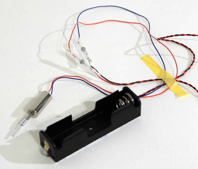
The engine kit is provided with one motor, one battery holder and two solder free connectors.
IMHO there are only two basic knowledge's you'll need to know to add electronics in your models.
- The first is a limited knowledge about soldering. I personally don't believe it's possible to light a model without soldering a few wires. Although ready made connectors may be used they are huge and can be used only where plenty of room is available and they can remain hidden. So inevitably soldering skills will be required. Soldering is not complicated as for most of the tasks we are accustomed to it just requires patience, experience. and often a third hand. :)
- The second is knowledge of polarity. +/-. That's easy. You know the red wires and the black wires :)
The only thing tricky is that leds are directional. They let the current pass through only in one direction. So all there is to know really is which is the + and - on the led.
The + is called Anode and is the long leg of the led. (some leds also have a flat on the + side)
The - is the cathode and is the short leg of the led

From there all you need to know is to solder the long leg of the led to the red wire and the short leg to the black wire. And then cut the legs. If you cut the legs before soldering you won't know which is + and which is -. Well there are other ways but I wanted to keep it basic :)
So managing the electronic is very simple. What is a bit more complicated is to ensure that the electronic parts are as hidden as possible in the model.
Electronics components are huge in our scale - even 1/32, cables are way too thick to be left visible, leds might be too bright and too big as well.
the most challenging to me at least is the hide the cables. A regular electronic wire (I use IDE cable from computer) is 1mm diameter. In 1/32 scale that's a cable of 3.2 cm. Way too big for cables running alongside the compartment walls.
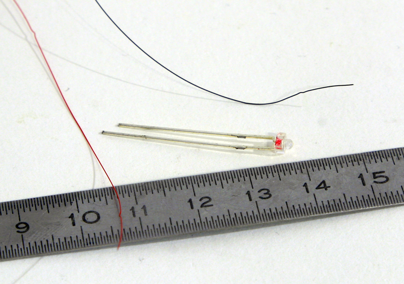
Luckily Magic Scale modeling made me discover these tiny cables:
They are 0.1mm diameter red and black and insulated! That means you can twist them together and use them as we would use copper wires to add wiring to our models, no risk of electronic short.
To solder them to leds you need to heat the wire first to melt the insulation. Then it solders like any other wire. They are perfect for our applications.
That's what I use when I can't make the cables invisible.
In some cases hiding the leds will require creativity. To light up the rear compartment I created a rail in plasticard. The rail is not in the real B-25 but that's an artistic licence I took to solve one of the problem.
Internal floodlight is perfectly made in scale with low warm white lights with short & rounded faces. They are not yellow but not too blue either. They are just perfect for flood lighting.
In other cases, it's dead easy to do:
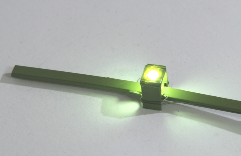
Let's take the wing landing light of the B-25. the kit has a plastic part for the spot embedded in the wing.
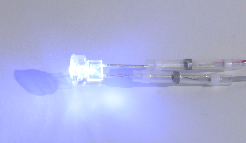
I'll use a 1.8mm white led long and flat face and round the face myself with a small file until I have a nice bulb shape.
Next I'll drill 1.6mm through the transparent plastic part and force the led Inside the kit part
and light it up
All that's needed now is to solder the led and connect it to the CB in the fuselage. It's a tad bright, but landing lights are supposed to be bright. I may try to dim it a bit though...
Let's do an engine test run:
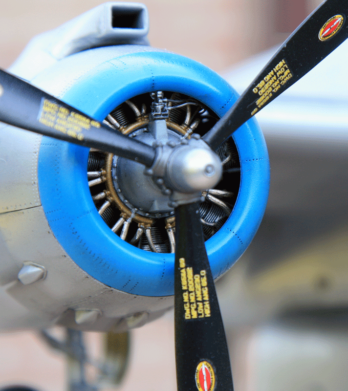
The engines are a pleasure to work on. The cylinders are painted aluminium's and given a wash of black oil. Most of the structure is painted black and slightly dry brushed in aluminum's. I also used titanium gold paint and the crank case is painted H307
I won't display any open panels so most of it will be invisible.
For that reason many of the PE parts for the engines from Eduard Big Ed kit won't be used.
The front face will get some more detailing.
As I said before I unfortunately won't use the AMS crank case because the Magic Scale Modeling motors fit to nicely the kit parts.
The props need some work to be used with the motor.
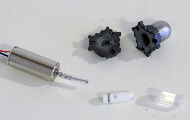
A transparent rod was cut to size and will be inserted into the propeller dome. The smaller white rod sits inside the transparent bigger rod.
The metal extended motor rod will go through both of them to ensure a good grip during rotation.
The white rod is cut smooth behind the prop governor. Normally the prop sits on the bit extended from the crank case but the fit is too tight and I am concerned it would prevent the props to turn freely and burn the motor. So I will cut the kit's crank case smooth to prevent that.
The motor sits inside the engine and the rod has been extended a bit with 1mm metal rod.
Kit's props are quite fat compared to the nice AMS resin replacement. The only advantages of the kit's part is that they sit perfectly well in he governor with the specific shaped holes.
AMS replacement pins are too thick. I'll cut them and replace them with small metal rods.
The prop is inserted on it's motor axis
And the motor is turned On. It turns with a minimum of vibrations. Concept is validated and I can move on.
It's now about time we get some paint on that model and get back to old fashioned modelism :)
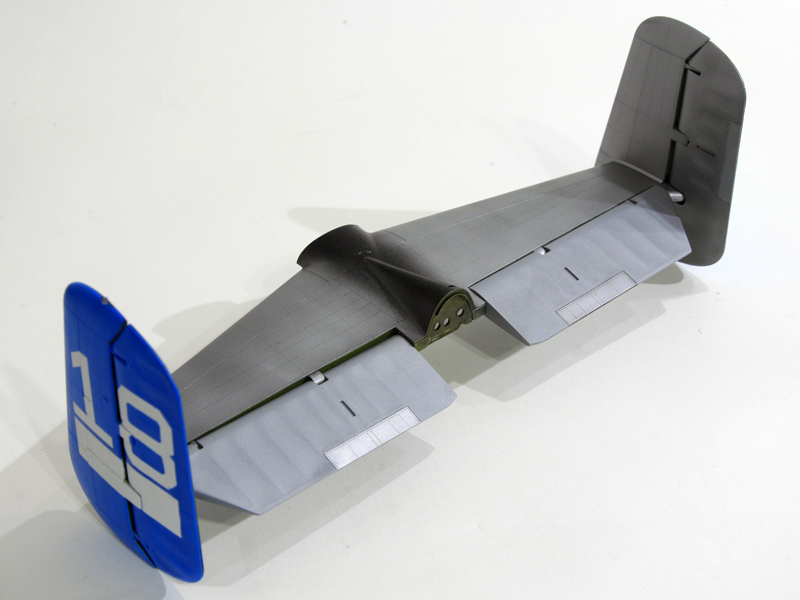
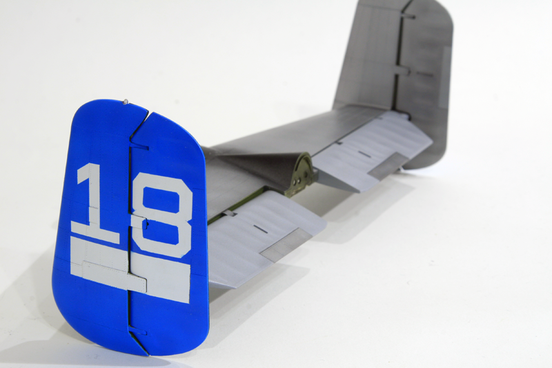
First the tails. Since I will do most of my decals i will spare me the trouble for the big ones and paint them straight on the model.
The easiest will be the big 18 number on both tails:
I started painting the tail in white, then masked the numbers and the white rectangle for the decal serials and then sprayed blue
Next was to try out some alclad tones on the model. Unlike some civilian restored B-25 Maid in the shade isn't very shiny. Matter of fact it's pretty dull.
I first tried airframe aluminum's thinking it was less shiny than aluminum's but soon realized that it is shinier and darker than aluminum's. not good for this project.
I then tried semi mate aluminum's and that was about the colour I wanted to have.
To illustrate the fabric on the movable controls I tried dull aluminum's which gives a very good difference from the metal of the airframe and painted the trim tabs in aluminum's to make them stand out the dull fabric colour.
The good thing about these non bright colours from alclad is that I can spray them over a coat of Mr Surfacer which for me is way easier than a gloss black should I have chosen aluminum's or airframe aluminum's.
Here are the test parts primed with Mr Surfacer:
and painted in the alclad colours referenced above:
Once they are all assembled on the tail unit, the nuances stand out pretty well:
The dark picture don't do them justice - It's hard to get good lights in this time of the year
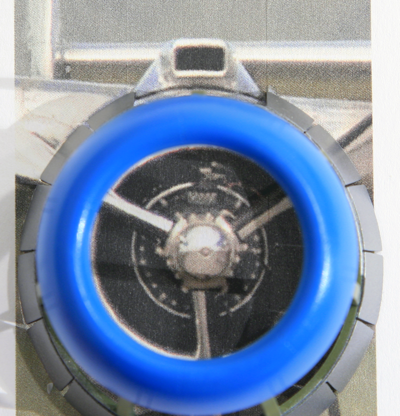
The carb intake challenge:
I knew right from the start that converting the engines exhausts and carburetor intake was going to be a huge challenge. After studying a lot of pictures adapted to scale, I calculated the front intake to be 8x5mm
I used a perfectly aligned picture of a B-25 engine and scaled it to the kit's parts. printed it and put the kit's parts on top of it. Then simply measured the rectangular shape:
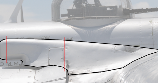
For the side of the intake, I tried to find again a perfectly aligned picture of the side view, scaled it to the kit's part and print.
The engine pods are undergoing surgical modifications:
First the Clayton exhausts were removed accordingly from the engine panels. The plastic was simply cut away from the parts. A plastic sheet was glued on the internal wall of the panel and the hole was then filled with Tamiya light curing putty. Once dry and sanded flat, I added Vallejo white putty and sanded again. Checked my work with a coat of Mr Surfacer and applied super glue on the holes remaining. Sanded flat again before the glue was completely cured.
One of the two hole is very close to the panel edge so it is very fragile. I broke two out of four panels at that tiny junction point. It's almost impossible to repair on the panel, but it will be very easily repaired once the panels are on the engine cowls, so I left that for later.
Accordingly, only the relevant internal exhaust ducts were glued to the cylinders (15, 22,16,10, 17 and 11)
The new exhaust collector that goes outboard the engine has been shaped by lightly heating a transparent plastic rod to about an angle of 80° then cut to shape. The outer wall thinned with the dremel.
To place it at the relevant spot a bit of angled sanding is required on the cowl flaps support plate and the exhaust is maintained in place with an extra angled support on the engine rear face.
Obviously two cowl flaps have been cut to let the exhaust pass through.
the exhaust will be weathered later on as the whole assembly still need to be primed and painted
The new carburetor intake has been built with 1mm plasticard to create a 8x5mm rectangle.
The intake lip has been sanded round.
The original intake has been cut to place the new one just for positioning purposes. Once happy with the result, I will further cut the old intake remaining sides and shape the new intake with milliput.
The biggest challenge is the rear openings. I wanted to milliput the whole part but if I do that I will have lots of trouble making that part, so I decided to make a structure in plasticard first and milliput around the structure.
Here are the attempts at the rear structure of the carburetor intake:
I'll now try to shape that specific part:
I first made the shape of the rear vents (?) with bits of plastics
To avoid having to build to whole engine nacelles before shaping the new carburetor intake I cut the top of the engine rear face supporting the cowl flaps so I could glue that bit on the top of the wing.
That way I can build the nacelle, engine and gear later on and probably avoid breaking the whole assembly as I shape and sand the carburetor parts.
I protected the wing with masking tape as my milliput work is usually messy :)
Once happy with the positioning I glued all scratched part to the top wings and started milliputting the new shape around the plasticard structure.
The milliput was smoothed with water to be as shaped and as smooth as possible
And then coarse sanded before removing the mask. Next step is to sand with finer grit and get it smooth.
I know it's far from the perfect shape. I took some shortcuts to make my life easier like having the rear part horizontal up to the vents where normally they should be angled down already. But I couldn't find an easy way to make that down slope.
The front face looks good though. The rest is far from perfect but this is an area where I am really not comfortable and I'm happy with the result I could get.
I will now finish it smooth and soften the rear edges a bit more before a first layer of Mr Surfacer
The next challenge after modifying to carb intake was to close the fuselage halves.
With all the stuff I added inside, and especially the wires and the PCB and the added rear compartment floor which is missing from the kit, I needed to ensure that all was working and fitting fine before closing the fuselage.
Anyway, before taking on that challenge, I wanted to do some real modelism and worked on assembling and painting the wings and the engine pods.
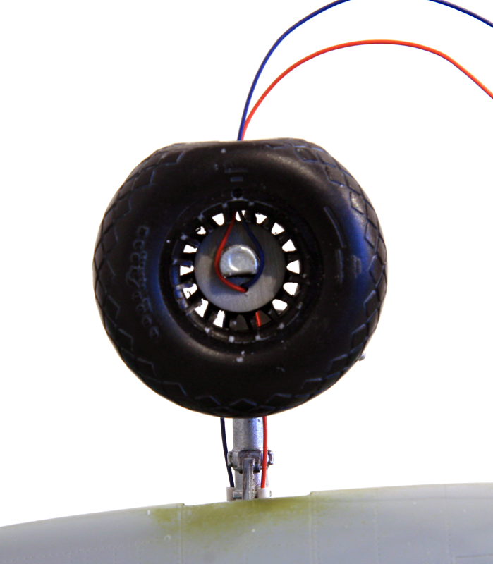
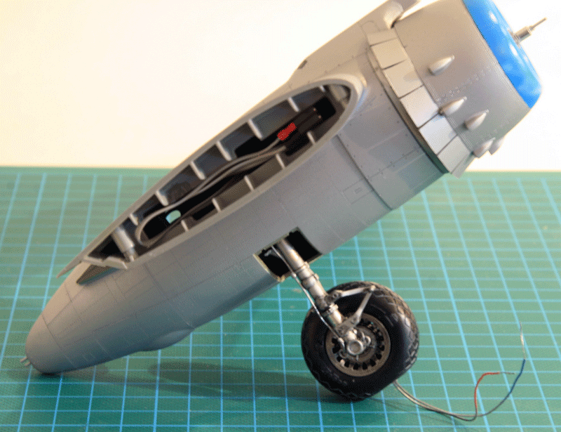
The trick was to decide where to go with the prop motor wires. I could go through the wings to the fuselage internal or go through the main gear legs.
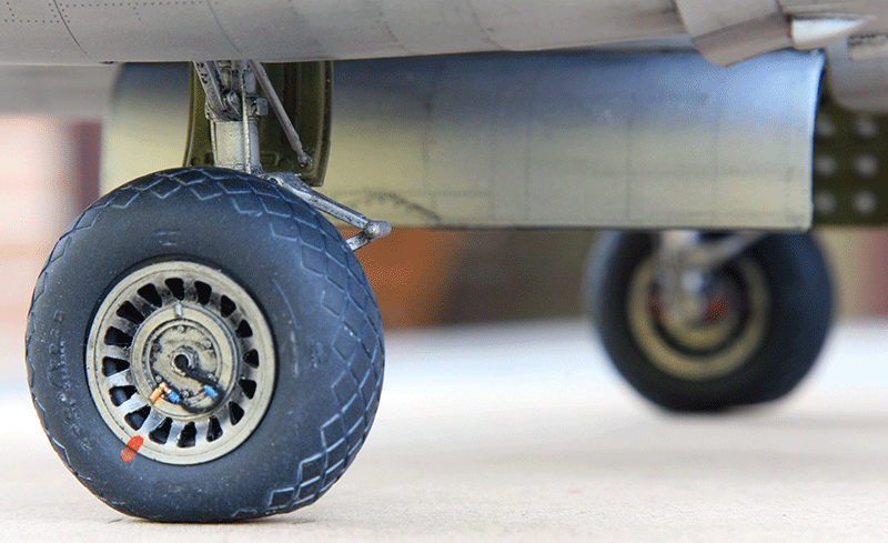
I decided to externalize the engine controls into the base of the model. So each wires from the engine are going to go through the main gear leg and tire into the base.
The wires replace kit parts J21/22 & J17/18. They enter the wheel, go around the axis and descent through the Tyre into the ground where they will go through the base of the model.
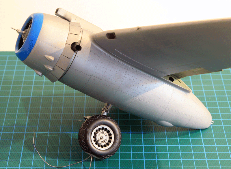
The pods fit fine on the wing and no putty was really necessary. Just a bit of sanding at the rear of the pod where it meets the top of the wing. the cowls were a bit more delicate to assemble, but that's mostly due to the motors fitting in there.
Inside the wings I wired the landing light and the position light (using scratch build fiber optics). These wires will go through the fuselage to the PCB placed behind the bomb bay.
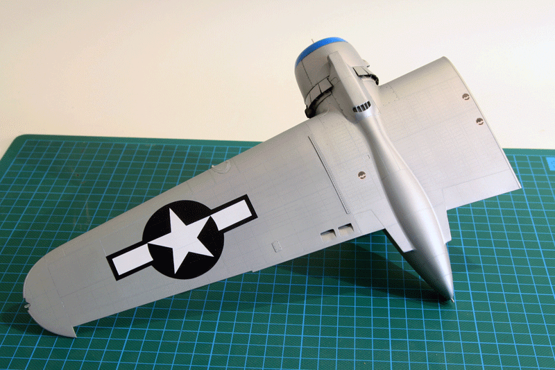
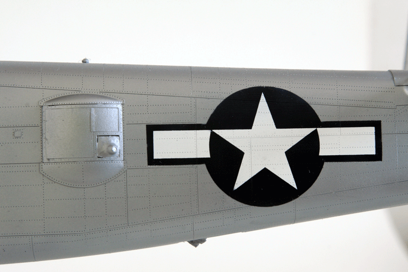
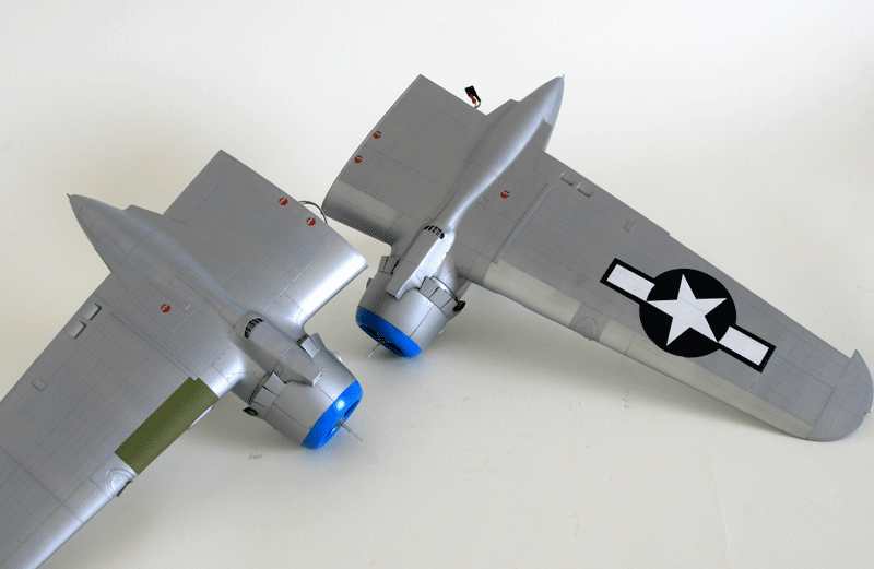
The wings were primed with Mr Surfacer 1000 and then sprayed straight with ALCLAD semi-Matt aluminum's. Maid in the shade aluminum's doesn't really shine. The alclad reacted fine on Mr Surfacer.
The US national insignia were painted with the Maketar masks which I used for the first time. I used the Kabuki version and they gave me plenty of satisfaction. It took a lot of time but enjoyable time doing paintwork which is by far more enjoyable than soldering wires for the led :)
No issue at all with kabuki on the alclad. Semi-Matt aluminum's is pretty solid.
I initially planned to place the printed Circuit Board (PCB) on top of the bomb bay but unfortunately the ceiling clearance is just too short.
I had to trick the rear of the bomb bay with a false compartment and slide the PCB in there.
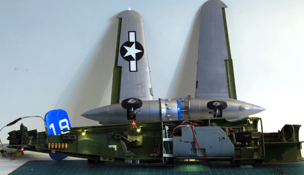
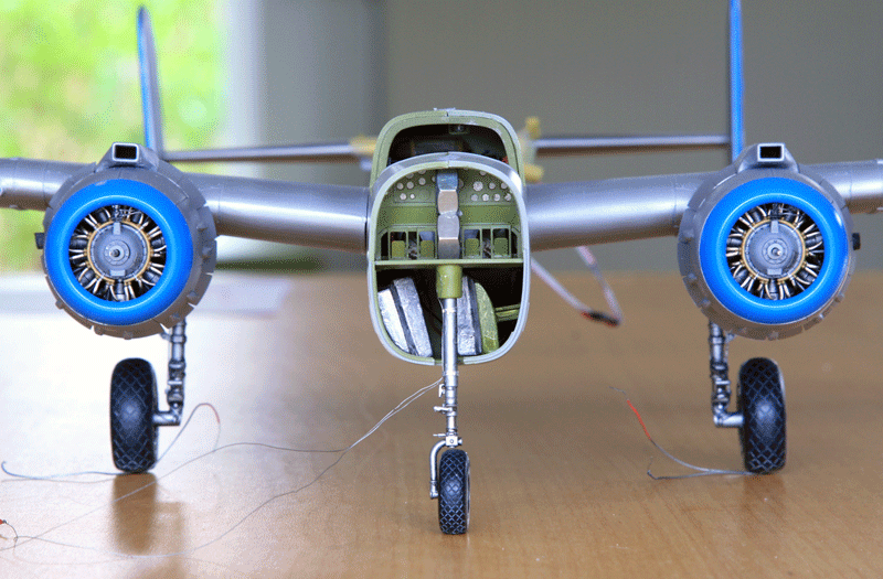
Checking the lights before closing the fuselage.
Two wires go out of the fuselage to the wings. To ensure the clearance for these wires I dug into the fuselage and bomb bay walls. The wires will go through the sliding mechanism of the wings. That will let me disconnect the wires should I need to disassemble the wings from the fuselage
The tail connects as well for the left top tail light.
Both Anti collision red lights flash in opposition, the rest of the flights are flood lights and remain steady. There are two in the rear compartment, one in the bomb bay, one in the front compartment and provisions for one in the nose compartment.
The wire providing power to the PCB are routed to the nose gear bay and will go down along the nose gear leg and into the Wheel into the base of the model.
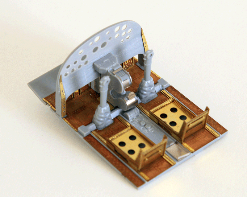
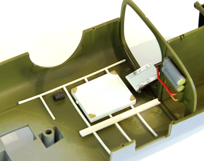
Seats were added into the rear compartment of Maid in the Shade. The cabin has been modified to transport passengers during airshow rides. I took a bit of artistic licence in the rear compartment seat positioning as the cabin will not be highly visible anyway.
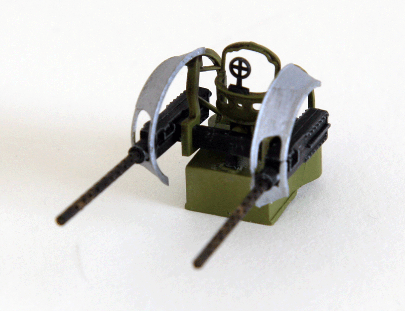
The .50 mechanism was quickly detailed nevertheless
Front compartment was also detailed. the top turret support will not be installed and instead two passengers seats were added on the rear bulkhead.
Seats are scratch built and I used the Eduard coloured seat belts kits.
They are far from easy to work with. They feel very unnatural because you can't really bend them naturally. If you do, the paint layer might actually pop from the PE.
In some cases, if you follow instructions you must bend a part at 180° to insert a buckle and doing so you will inevitably destroy the coloured layer.
Probably the last time I use these, they were included in the Big ed set but honestly, they are not worth using.
A simple painted lead sheet and cut to size with PE buckles give much better resin than full PE coloured seat belts.
I heard a lot of good about the HGW fabric seat belts but I never had an opportunity to test them yet.
The scratched floor in the rear compartment might create fitting issues when closing the fuselage so I added some guides to ensure it was moving above the internal support. In dry fit attempts, the floor got stuck under the support creating a gap at the fuselage joint.
I had a bit of trouble with the Terry Dean nose weights. The longer weight naturally goes on the side opposite the passage to the nose. As the cockpit floor was glued on the other side, care was taken to ensure the weight didn't conflict with it.
So I had to angle it a bit to ensure I didn't create fitting issues.
I couldn't really sort the shorter weight position. the cut and the curves didn't get me a natural position so I ended up improvising. I put some spacers from the left wall so the nose weight wasn't too visible from the nose. As I didn't build the passageway, I didn't want the nose weight to be fully aligned with the large hole visible from the nose.
I don't want these weight to move so I glued them firmly in place, and made sure the glue was well dried before closing the fuselage to ensure liquid glue wouldn't soften the plastic.
I ended up with a bit of an awkward position with the nose weights, but who cares, nobody will know :)
Don't mind the tail;, a wire makes it unbalanced.
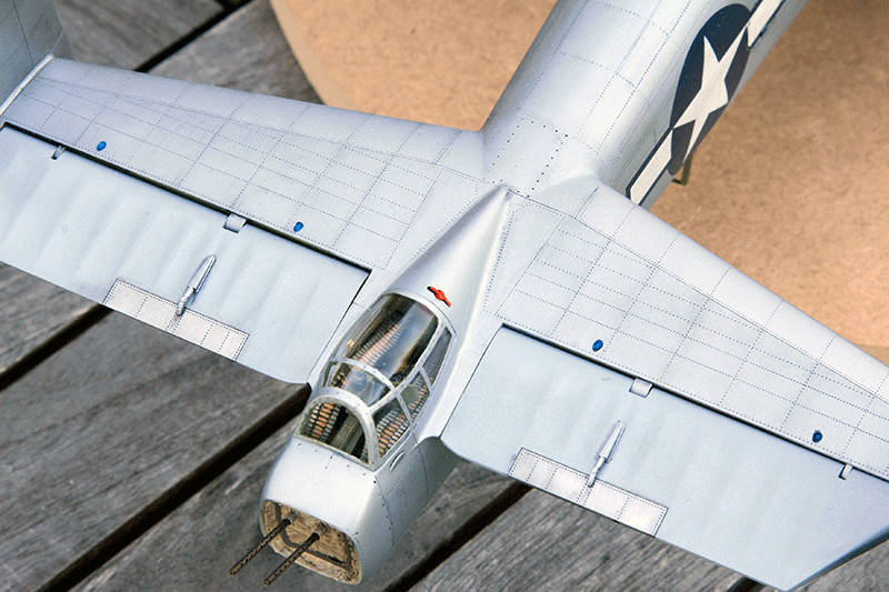
It's a milestone in this build. With the fuselage finally closed, the model finally could be assembled. That's were you realize how huge this beast is!!
some minor detailing of the gun pods:
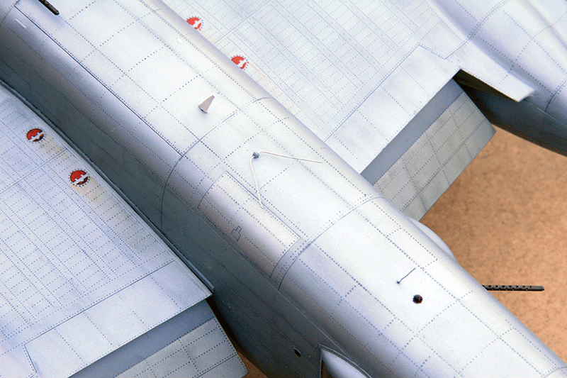
The fuselage is ready for priming, ailerons and rudder flight are already painted with dull aluminum's for fabric covered surfaces, the tabs are aluminum's and contrast heavily with the flat parts.
The parts inside the wings when the aircraft is clean are painted dark grey
The flaps which are metal are painted semi Matt aluminum's, like the rest of the Aircraft
The US National insignias on the fuselage were painted with the opposite masks method.
This allowed me to tests both method of mask painting. Have a look at the specific articles about using masks if you're interested to know more.
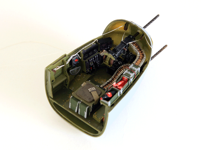
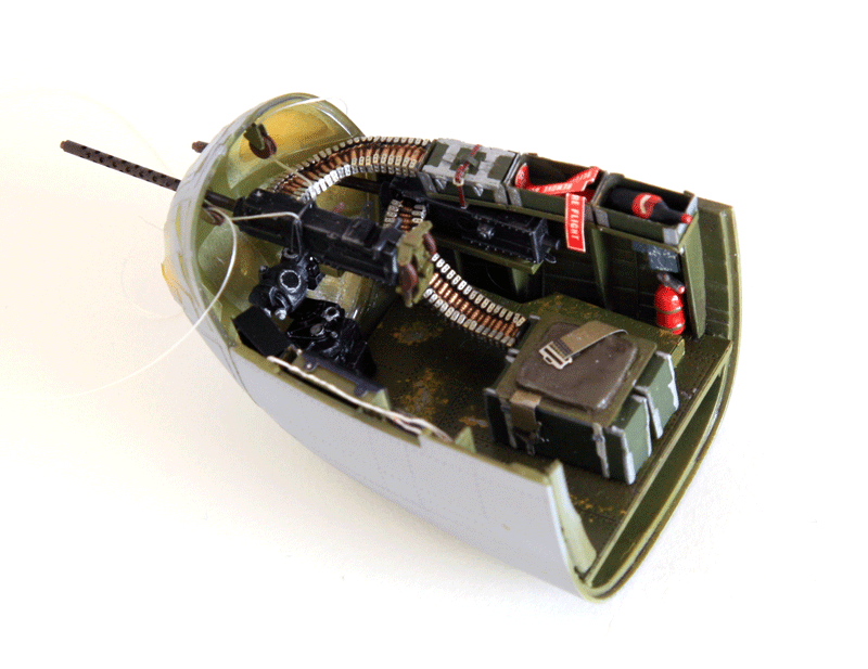
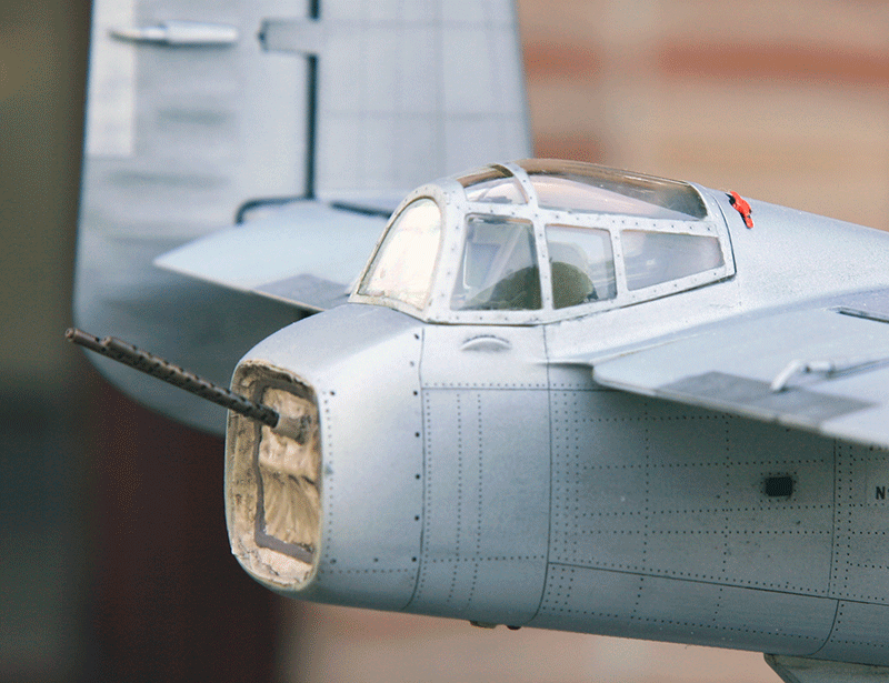
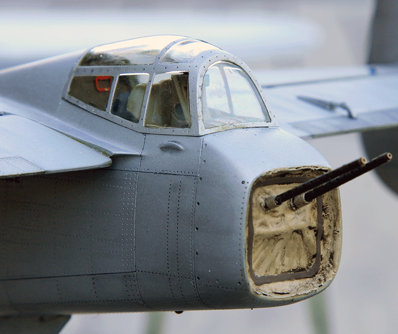
Lets work on the nose section which is a small model by itself within the model:
The Eduard ammo boxes were cut shorter - it's actually very easy to make them lower as the usual ammo boxes by simply snapping both top side off.
Two of them were left opened with Remove before flight tags and an unsecured bottle (not a good idea I'd guess)
And some details:
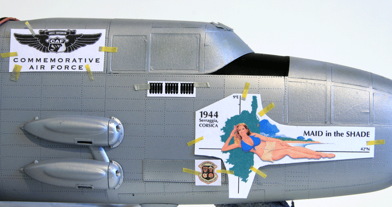
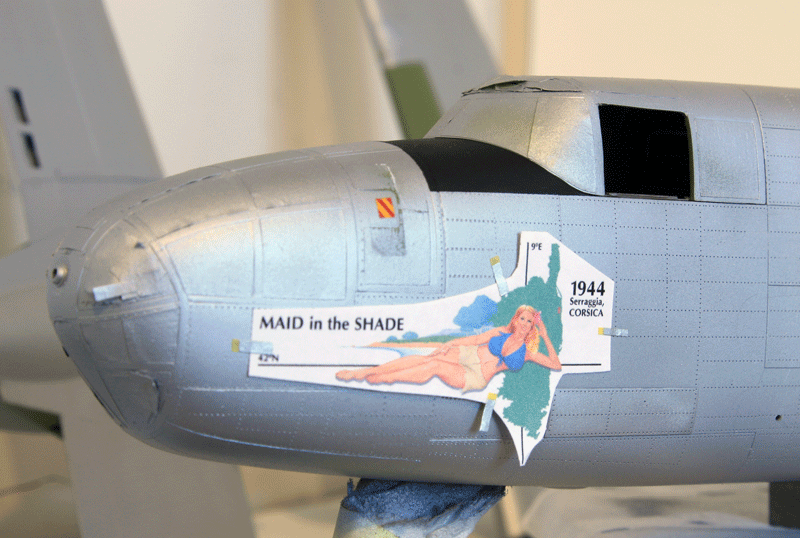
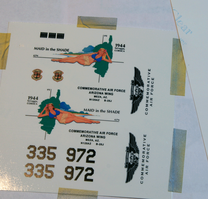
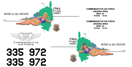
Decals
As i pointed out earlier, this project will require homemade decals.
I usually printed my decals at work on a laser printer. Unfortunately that old laser printer has been retired from service.
I thus turned to ink jet printing on the home printer. I was a little bit concerned about ink jet being as good in quality as laser, but I'd give it a try anyway.
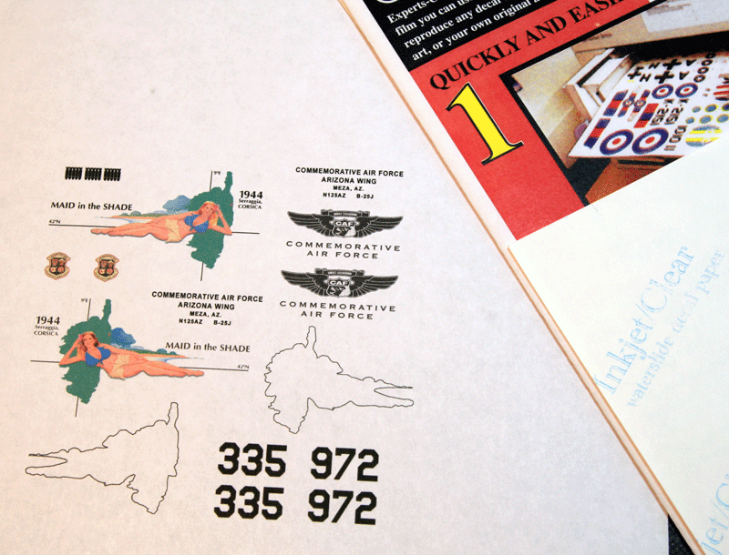
First step was to source a few sheets of ink jet decal paper from expert choice decals.
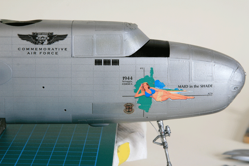
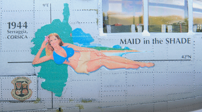
The artwork were redone as well. Maid in the Shade recently had the pinups repainted. My original artwork used the old pinup design. Since I'll do the 2016 version of Maid in the Shade I needed to change a few things.
The first step after completion of the artwork design is to print the decals on plain white paper and check dimension and fitting on the model:
Once satisfied with the dimensions, I then taped a piece of transparent ink jet decal on a paper sheet and printed the decals
I'm pretty glad with how this turned out. The ink jet result is pretty good and much more vivid than on the white paper.
Matter of fact, this may be much better than the results I had before on the laser printer.
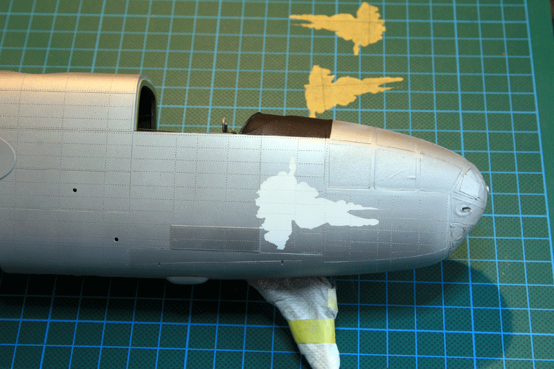
The problem with homemade decals is that some light colours might not be opaque enough to cover the sometime dark paint on the model. In this case, the aluminum's is light but I'm a bit concerned about having a dull pinup color if I simply put the decal on the model.
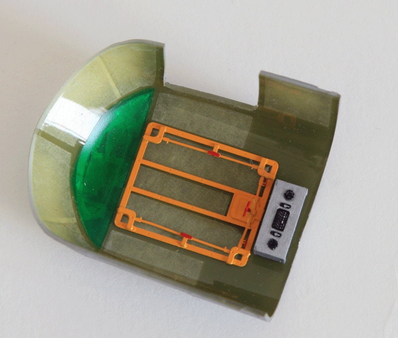
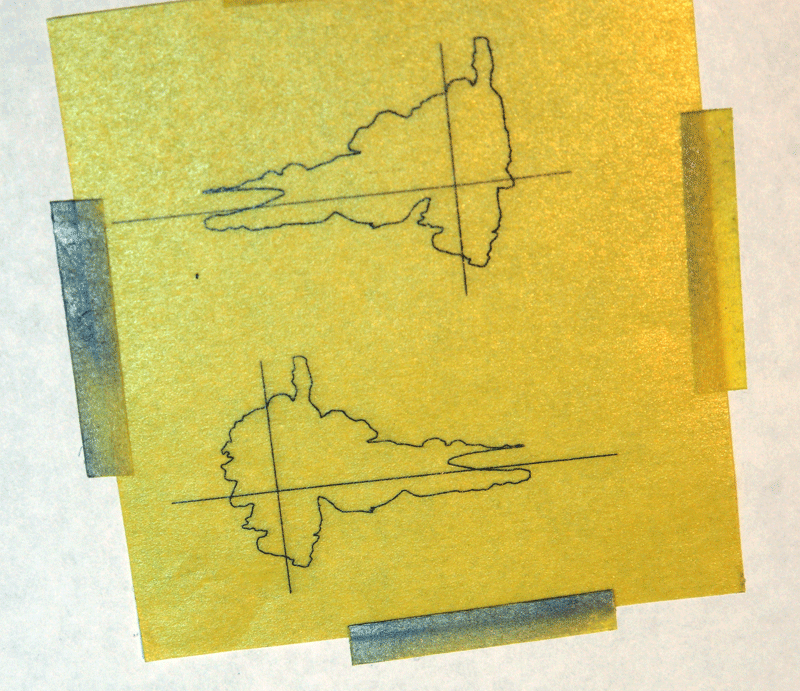
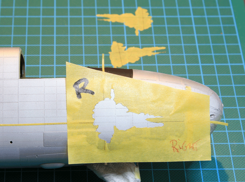
To give the decals more brightness I decided to create a mask so I could paint the background of the artwork on the fuselage in white before applying the decal:
I created a contour mask and printed on a blank sheet of kabuki paper.
I'll just need to cut the mask and use the black vertical and horizontal lines to align the mask on the model, and paint a thin white layer as background:
As you see, I had to cheat a bit by rounding the contour of Corsica to make the cutting a bit easier :)
First step was to carefully cut and align the nose art mask on the nose:
then paint white:
And apply the decals.
The large nose art decals are very thin (on purpose) and very fragile. So I didn't have the luxury to move them a lot. They were also very sticky and I was very concerned I might tear them while moving. So I decided to live with the small bits of white outline I have left.
I will correct that later one with a bit of paint touch ups.
There is no doubt that the white background mask was critical. The decals were indeed very transparent and wouldn't have stand so good on the semi Matt aluminum's without the white background.
To some extend you can see what would have happened with the small brown patch. The decals are dark colours but still don't stand enough of the airframe colour. The nose art being light colours would have been much worse
The tail decals were much easier to place:
Testing some variation of metal colour on the wings. Alclad aluminum's for the leading edge (except the leading edge in primer which seems to be a 2016 feature of Maid in the shade (that's probably going to be repainted soon on the real one but I love the spot of color it gives the aircraft :)
I also made some tests about which varnish to use before the decals. I never tried the Gloss cote from alclad and I wanted to but was concerned a bit with the subtle oil wash I'd give after decals.
Usually I always ensure that the gloss coat is opposite to the wash (if wash is oil, gloss is water based)
So I tested on the inner flaps and when I apply wash (tamiya panel line accent) over the alclad gloss coat, you can clearly see that the wash diluted the varnish and a gloss/flat difference clearly appears.
I think I'll revert to the old safe value acrylic X22 for basic pre decal gloss coat.
Flight crew
As the model might have lights on and engine running, i needed a flight crew. So let me introduce you Billy and Mike
Billy has just finished starting the N° 2 engine and after a quick check of the gages is telling Jamie who's on the ground manning the fire extinguisher that the engines gages are OK. :)
Both figures were assembled from the scrap box. The arm were adapted to fit the B-25 cockpit. Mike is holding the yoke while Billy gives a thumb up through the opened cockpit window. He also has checklists on his right hand.
Initial assembly
Dry fit in the cockpit.
The main concern was to ensure that the pilots wouldn't interfere with the transparent canopy part when placed on the fuselage. To make sure it fitted I had to lower the seats a bit. I also cheated a bit with the yoke to ensure that Mike had it firmly in his hands.
The seat belts which are not weathered yet are made with the Eduard PE buckles. I discarded the Eduard PE belts as it's way to o hard to bend them around the clothes curves. I replaced them with lead foil.
The David Clark headsets were scratched.
Not many civilians pilot are available so I did my best with my limited experience on figure painting and the limited parts I had at my disposal.
Once the canopy will be closed I'm pretty sure it's going to be enough
Not much of the pit will be visible once everything is closed down. I nevertheless tried to make a compass on the main glare shield which should be well visible
The rear gun cover was made from aluminum's foil. Earlier in the build I considered the Grey Matter Figure part which is a much better than the kit's part which is really bad IMHO.
But Maid in the Shade has a real flat canvas so even the GMF part wouldn't cut it.
Making the part was very simple, just cut aluminum's foil, paint in tan and done. The extra zipper was also made with aluminum's foil. It's a bit too wide, but that will do.
The guns are brass guns from Master. They are actually coming from the B-17 set. I will never use anything else than these brass gun. They are way better than the plastics ones and much easier to use than the photo etch gun you have to roll closed.
These are not painted, simply burnished with the AK metal burnishing fluid.
Maid in the Shade features modern radio and navigation systems and the antennas are different from the WWII models, they needed to be scratched.
Quick and dirty work on the top fuselage in front of the (modern as well) anti collision light:
The horizontal stabilizers have 4 small blister blue lights. These were made with the templates Eduard PE fret provided. There are a lot of them on the Eduard PE and I always keep these.
Just heat a bit of transparent sprue Under a candle and press it in the template while hot to get a nice nav light.
There are actually 2 more on the vertical tail, but they are left transparent.
Note also the added red handle to release the tail gunner canopy and I'm pretty happy with the tonal differences between the fabric covered controls and the metal parts of the tail and trim tabs
The main wheels got some detail painting. Can you guess that there are actually 2 wires descending from the wing to the base for the engine power in there?
Custom nose art decals printed on regular ink jet decal paper with a white mask applied before decal. It's the worst of the two, the other side actually came out much better:
The led in the top turret compartment illuminates the cockpit as well:
The converted carburetor intake:
Top view of the cockpit and bomber compartment
The modified exhaust on the outboard of the engines
AMS propeller
The light Inside the waist compartment saves a bit the invisible details Inside the fuselage
Pictures of the finished model:
Engines OFF
Engines ON
The base has three switches. One for the left engine, one for the right engine and one for all the lights.
The separate switches for the engines allow to have different starting engine configurations
The finished model featured in a short video where engines and flashing lights are better seen:
Subscribe to:
Posts (Atom)