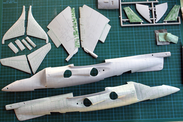
This is an Airfix 1/24 GR1 original boxing that I will try to convert to a GR3. This model is almost as old as I, so I'll treat it with utmost respect.
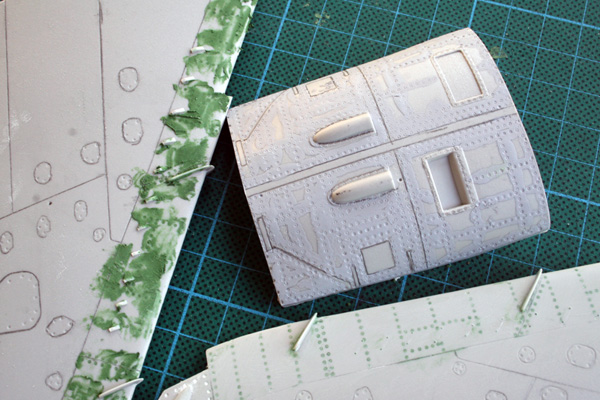
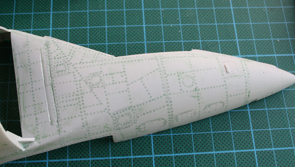
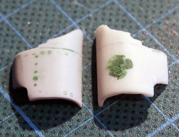
First task is to fill all those nasty rivets. I tried different filler such as tamiya Putty, two components, Mr Surfacer 500 and Green squadron putty.
My choice will finally be the last one, as it's easy to sand away, dry fast and provide a good contact between the plastic and the filler.
Most of the work is done on the fuselages, tail, gear doors, wingtips.
As I said, this is a GR1 and I even don't have the laser nose and PWR fairing, so I sourced some resin and PE plug.
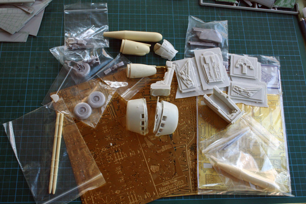
Flightpath GR3 huge kit, the second BLU and loader, the heritage resin cockpit and the heritage intakes. The guys and gals at flightpath were also very kind to provide me a laser nose, and I got part of the PWR fairing and an extra nose from a fellow on ARC a while back (many thanks).
I wrote Airfix and they agreed to sell me the new decal sheet from they reissued GR3
At this stage I plan on doing a 1st sqd bird on deployment to Norway with the white paint covering the green.
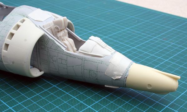
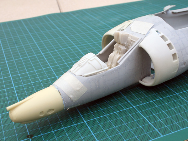
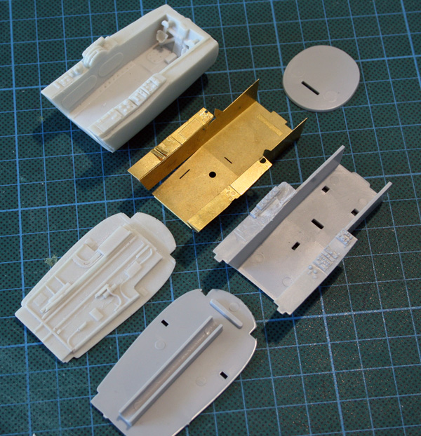
here are the first dry fits. The resin cockpit and the intakes have been cut and it's always a great motivation to dry fits the parts all together (thanks Bluetack) to see some aircraft shapes.
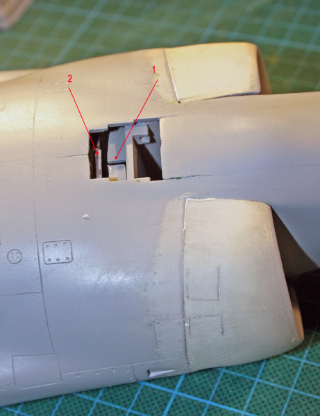
I almost cut the extra resin on the nose, but finally decided against it and hollow the nose a bit so the recess enter the fuselage and makes a solid joint.
The PWR fairing from the flightpath PE set seems too large. From drawings, it should be 9.6mm high in 1/24 but it's almost 11.5mm, so it had to be modified.
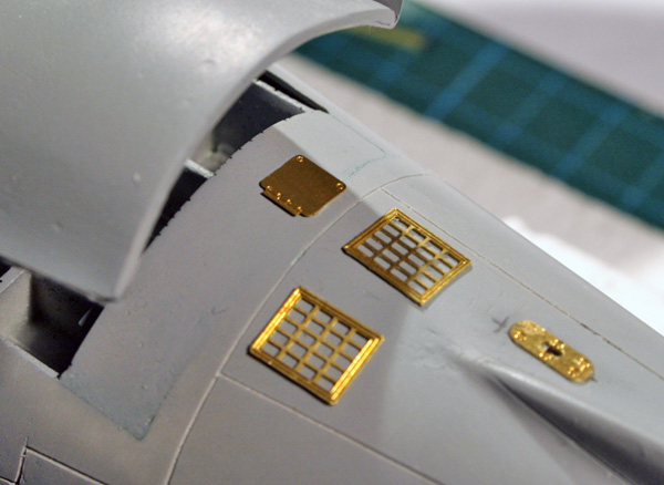
The main wing was assembled and I started detailling the port wing.
It's the first time I use the Gator's glue for PE parts I discovered on this very website instead of my usual Cyano glue. Much more flexible because you have more time to place the parts correctly. A very good product which I recommend. The bond also seem quite strong after drying.
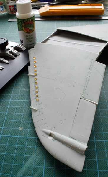
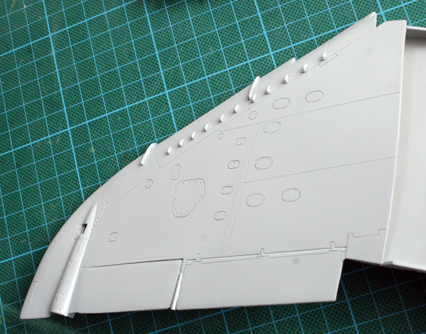
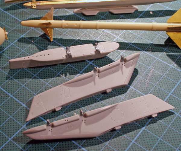
Here's a rundown of the parts I detailled, beside filling the rivets redoing the engraving and trying to thin all the trailing edges (flaps, aileron & tips):
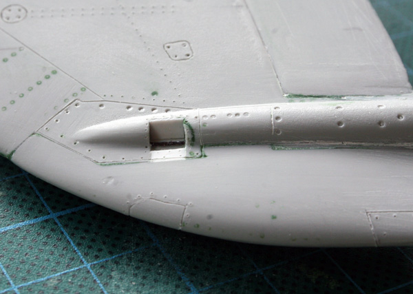
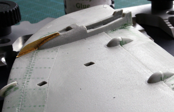
- The RCV exhaust on the top of the wing was opened and detailled (they are nonexistent in the airfix kit :? )
Strangely flightpath didn't provide any PE parts either. It could have used some.
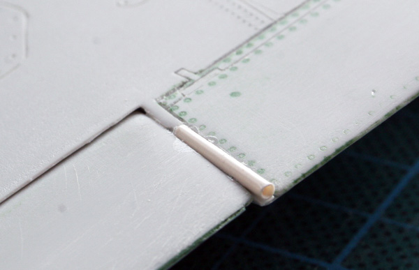
- The fuel vent between the flap and aileron was redone with plastic rod.
- The vortex generators are added from the PE set. I also redid the wing fences in styrene before realizing they were also available on the PE fret :blush:
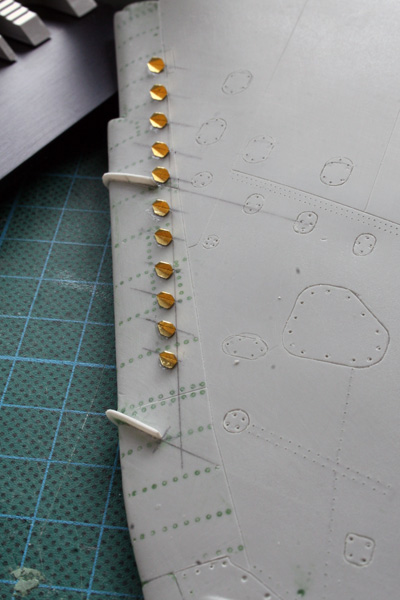
- The fence on the outrigger was thus made with the PE parts. I also remodelled the two ailerons actuations covers. There was a huge gap in the middle so the aileron can be lowered. In my case, I glued the aileron in neutral position, so the covers needed to be filled in the middle. that was done with styrene and putty.
Then the wing received a coat of Mr Surfacer so I can now check the engraving and finish the sanding/correction process.
Some cockpit work:
The choice between plastic, resin or PE: the plastic one is no option, I don't have that kind of skill
The resin looks fine but lots of fragile stuff are broken (wires) and suffer from a lot of bubbles especially on the front panel.
All three are different in sizes (?) and I can see mistakes on the resin and plastic. On the other hand, some components won't be modelled correctly in etched brass only.
So I decided to make a mix of all I have available.
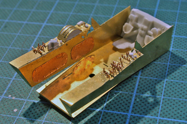
The tub is done in PE, detailled with some plastic and copper sheet bits where appropriate. the swicthes are made with wires, they are too thick to my liking but I couldn't make holes in the brass smaller than that so I will have to live with it.
I wasn't convinced by the way the rudder where made in PE, so I cut the resin ones and fit those instead, they are much better
The front bulkhead will be the kit's piece and the rear bulkhead will be the resin one.
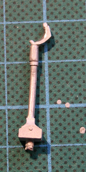
The Flightpath control stick is really not good enough for the job in that squale, much too square and lacking details. I need to replace it. I hesitate between remodelling the white metal or making a complete new one ?
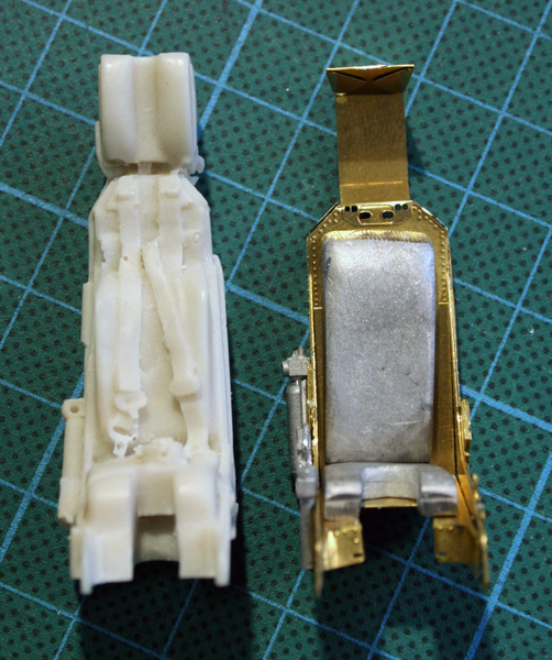
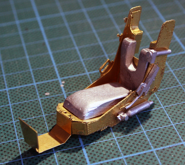
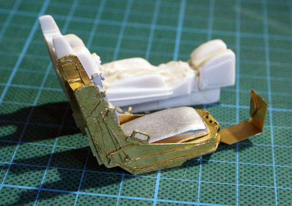
I also s tarted the PE seat although I haven't decided which one I'll use in the end. It seems the headrest of that seat can be elevated and the resin one is as low as possible. Although all pictures I have seen show a gap between the headrest and the main body of the seat. This is something I could easily do with the PE seat, but not with the resin seat. Although as you can see on the picture below, the resin seat has the main body of the seat quite higher than the PE seat...
All three seats have the parachute badly modelled in any case. At this time, I favour the PE seat.
I must say the flightpath kit is a really great addition, the detail are really great and even if the instructions could be better, careful studying before gluing makes the trick.
They were done with 0.25mm wires and the knobs were made with a punch and die set.
I can now weather the pit and start working in the internal fuselage, that's where we all seem to break our tooth :)
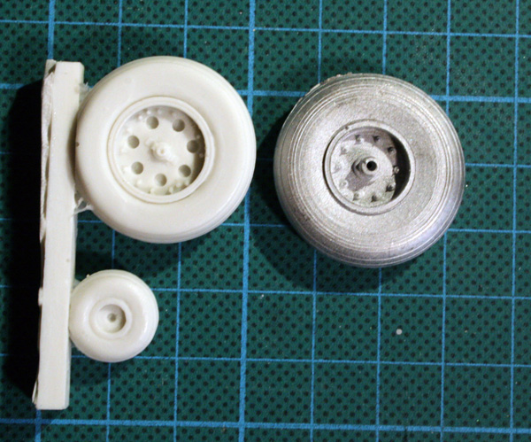
Since initialy seeing them, I though the flightpath metal wheels are too thin and too big. I decided to get a shot at the heritage aviation undercarriage set and the wheels looks much better imho
I'll let you judge by yourself with the below pictures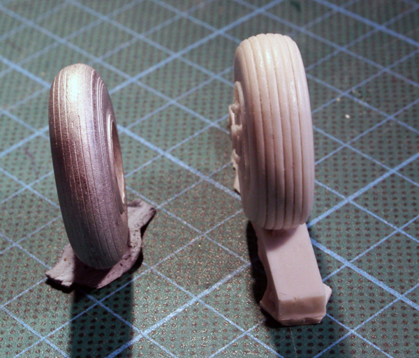
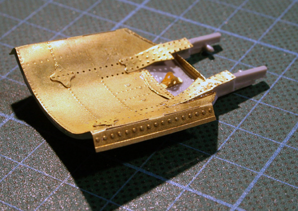
I also got their speedbrake bay which looks quite good as well!
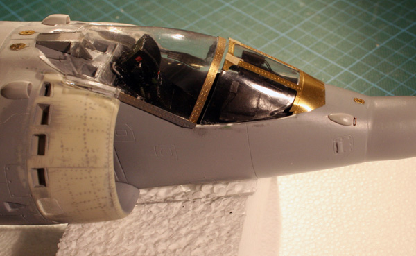
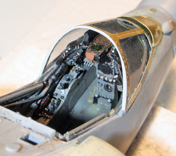
the seat was finished and painted - I just need to work on the harness. The tub is complete as well and assemble with both bulkheads, so it's ready to be put inside the fuselage. The sidewalls are ready too, I have some more PE parts to add under the glareshield on the walls.
The glareshield was heavily detailled but I know I will have problems making the windscreen fit with the heritage aviation resin glareshield. I'll have to find a wayI cut two missing vents on the canopy slope behind the rear seat as I plan on detailling that area once the fuselages are glued together.
The engine has been quickly assembled and primed. I won't detail it since the harrier will be totally closed. I install it just because I'm too lazy to make new attachment points for the nozzles.
I know it's going to be a hard fight getting all the stuff aligned properly in there.
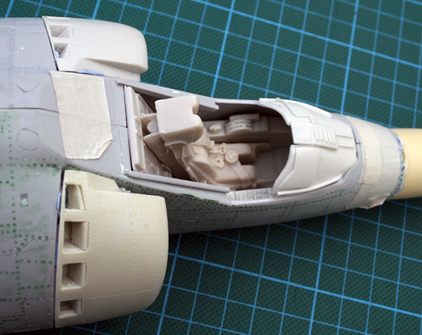
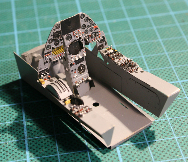
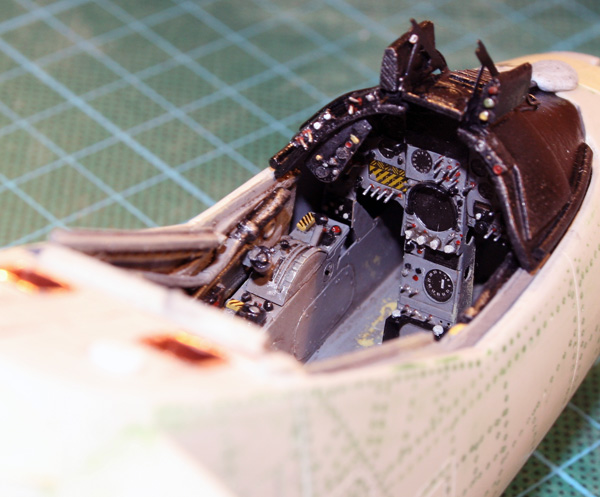
Here are two quick pictures of a cockpit dryfit. Most of the piuctures of the GR3 cockpit I've seen are pretty dirty, so mine is as well.
I feel the hardest part of this build is to close the two fuselage parts together. lots of planning has to be done to avoid future problems and the lack of internal details needs to be though of too.
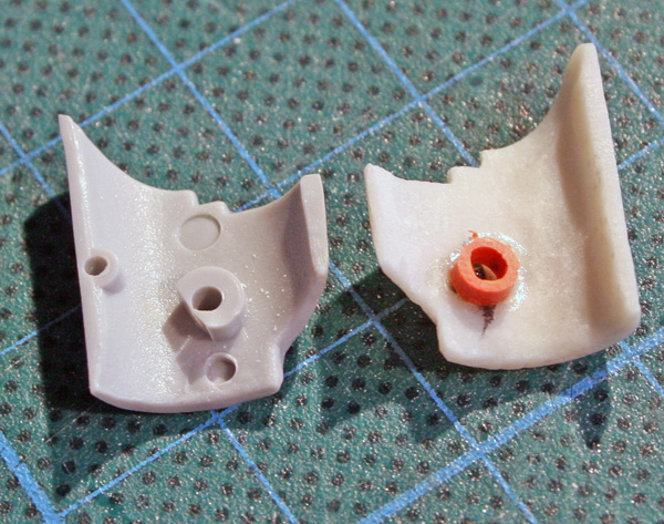
So I decided that the gear doors will remain closed on both the nose gear and the mains.Usually the mains are closed on the ground anyway. That's not always the case for the front gear doors though, were most GR3 pictures I have seen have the nose gear doors open when the jet is cold.
Well, mine will be closed - I don't want to spend lots of time detailling the nose gear bay.
I'm also adding a new airbrake bay which really is too shallow in the kit and really badly done. The new one come from Heritage aviation and is very nice. That will not be easy to fit since you can't access it once you close the fuselage. Maybe a better approach would be to leave it out and insert it from outside once the 2 fuselage are glued together. Not easy, but the joints may be better distributed this way. If you glue the resin tight on one side, you may end up with a tiny gap and the other fuselage side? Anyway, it's pretty minor and nothing a bit of putty can't solve
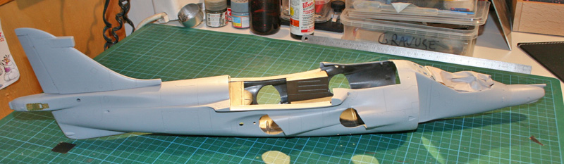
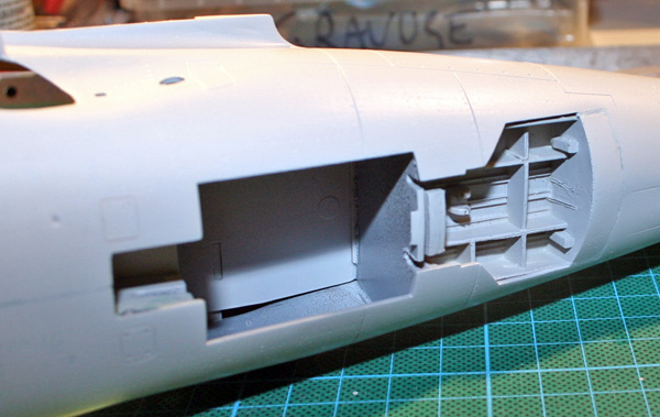
The fuselage is now glued together, sanded and primed. Still a long way to have a perfect finish but I needed the first coat of primer to see the inversed rivet work.
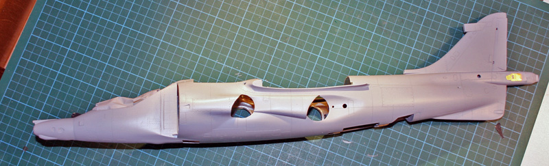
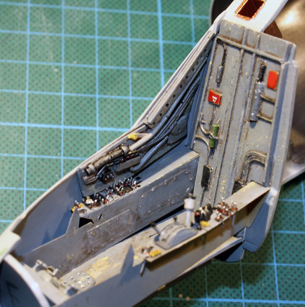
Here's a very bad shot of the airbrake bay, that's the heritage resin part. It's very well thought of and fits quite nicely
Glad i can close the main gear doors because that bay really is empty.
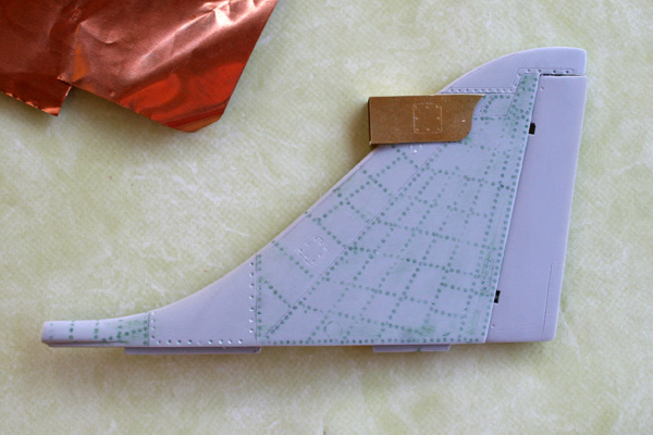
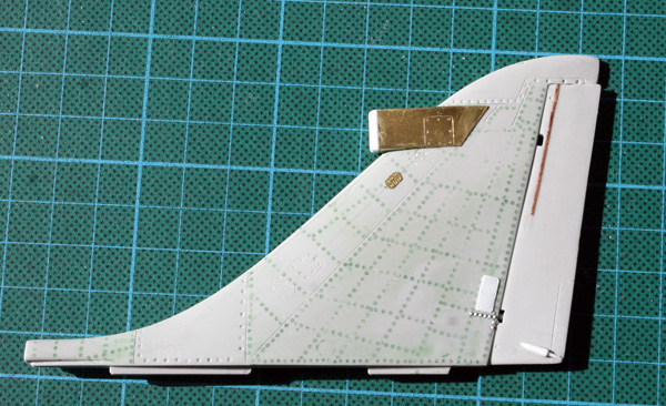
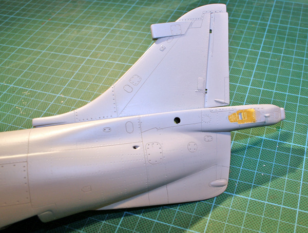
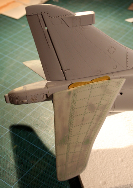
Finally a shot of the tail, my best loving part so far :)
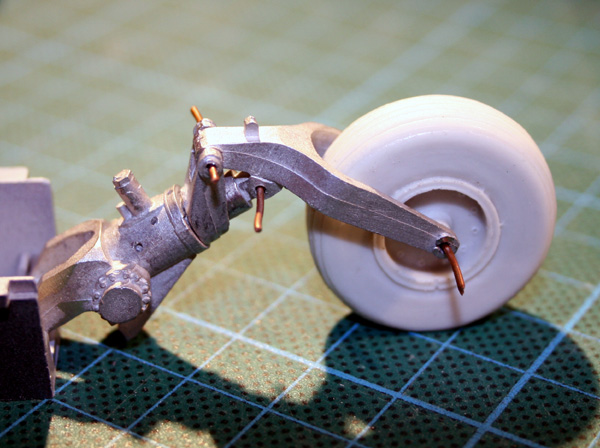
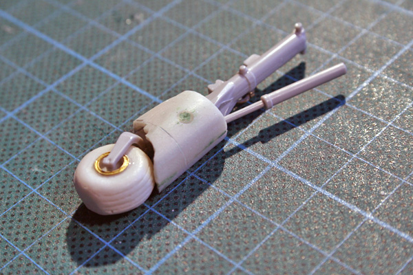
Before fitting the nose gear bay inside the fuselage, I needed to make some choices for the nose gear
Flightpath wins the nose leg, Heritage wins the wheel. The kit looses all the way. Dryfit with metal rod insterted for the pivot point.
I was very close to use the heritage leg instead og the FP, as it's way easier to rotate the nose wheel a bit but the quality of the casting finally ruled that one out.
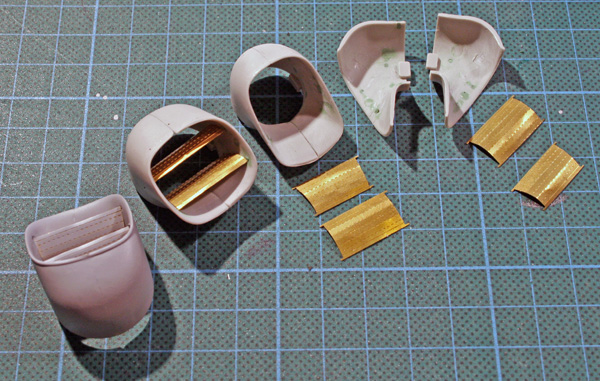
Next are the fitting of the intakes. Theses have to be carefully fitted, with lots of sanding here and there before gluing to prevent an ugly sandjob on the very visible areas of the outer intakes.
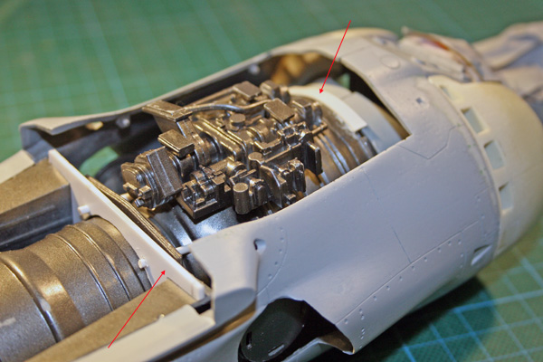
Here are some pictures of the engine installation...
I left the engine out while assembling the fuselage against the instructions. Of course I did try beforehand to see if the engine could be placed in a closed fuselage. it works fine, if you insert it nose first and then rotate it in.The main problem of the engine, is that it rests on the aft support glued on the fuselage and the forward part of the fuselage rest on the internal intake parts.
So it means there's no supporting part below the forward part of the engine and that's what makes the positionning and nozzle alignement so hard IMHO. There comes the screwup :)
I forgot to check that the internal intake duct parts would be positionned correctly inside the fuselage for the engine to rest on. Since I used the resin intakes, that was a major screwup!
No idea if that would have been different if I had used the kit's intakes?
The kit intake ducts were glued on the resin intakes and then those 2 were glued on the fuselage. The internal parts thus form a round duct where the front of the engine will be glued.
Well, at initial placement, the engine was 5mm to far aft and nozzle weren't aligned at all.So I had to get on the saw and remove a few mm of that internal duct without removing the intakes (they were already sanded of course) I knew I could never see that one right, so I cut more than required on purpose.
I then placed a small 4mm support for the lower front engine so it would be resting as well on the lower fuselage, this support was glued just aft of the nose gear hole.
I also made a engine support piece in plasticard to support the engine from above, right in front of where the wings come. That wouldn't be really necessary but I would hate to see this engine move once all is closed ... so better safe than sorry. I finally glued some plastic strip around then engine front blades to secure it to the intake ducts. From then I could secure the engine in place assuring correct alignement of the nozzle.
Checking the nozzle attachement points alignement ...
Nozzle step,
From reading other builds, I knew that I could sand off the alignement points inside the two parts nozzle, they don't really help to have them properly aligned.
So I started by doing this and filling the mould marks as well as the hole for the internal parts since I will replace them with PE parts from Flightpath.Then each part is sanded, glued together and sanded again. Then the PE is added. the PE pin go straight into the putty filled hole and they bore through just by pushing them in, so it's really easy.
Here's the progression:
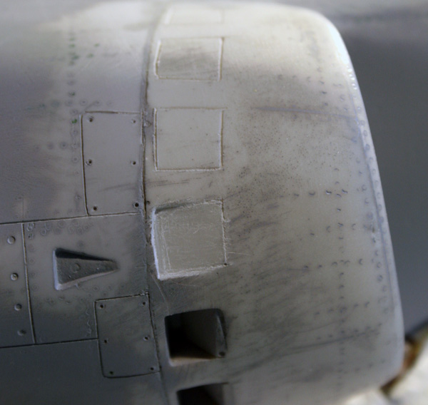
Fuselage and wings and engine covers have been glued in place.
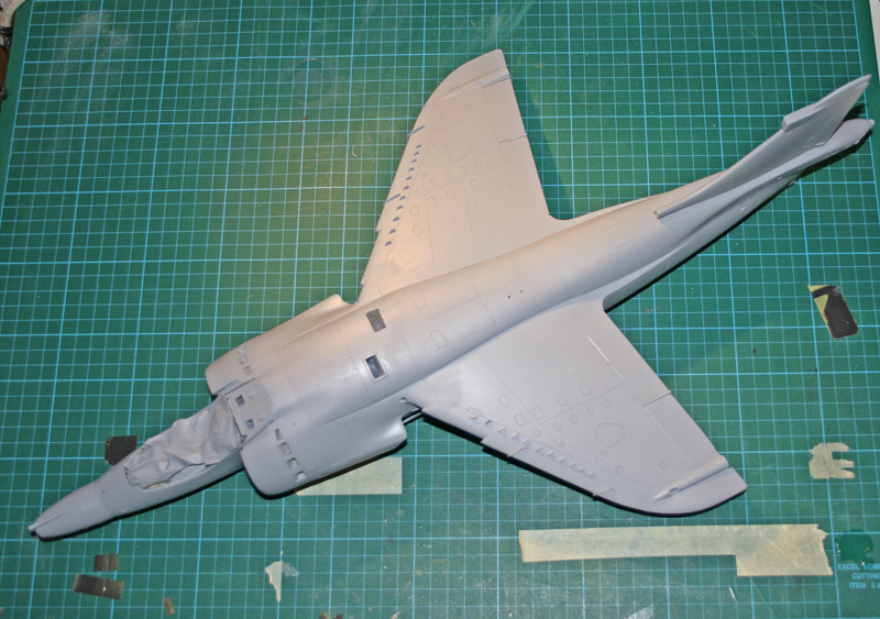
Not an easy task, the wings go on fine, the problem is mainly the engine cover, but I had been warned :)
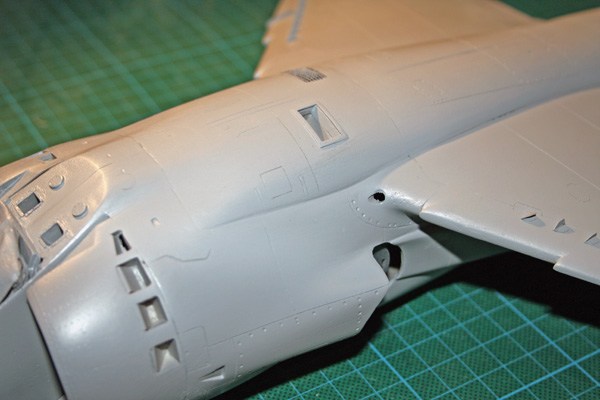
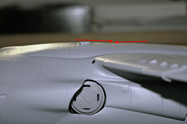
First problem is the kind of junction I should have between the engine cover and the fuselage. It seems the forward section is flush and the rear section (closer the the wings) is flat because of the doors being closed there.
Not easy to reproduce and I lack some specific pictures of that. I think I'll follow my instincts and make it flush where there's no door and add a strip of styrene where the engine access door meets the fuselage.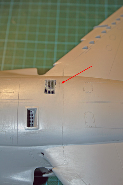
Early during the build I made yet another error. I sanded the inside of the engine cover so the mesh would be closer to the top surface. Bad idea. When sanding the engine cover flush with the top of the wings, I went through the thin plastic. I'll probably have to cut that area out and start again.
The amount of sanding between the engine cover and the top of the wings is quite important, and of course as A result I create a sort of V shape at intersecting line between the two panels.
I'm not sure I will fix that one easily... maybe some milliput will be needed here but I'm concerned I may do more harm than good ...it' looks bad when looking at the model from the side. I've seen this default on lots of 1:24 harrier, I know why :)
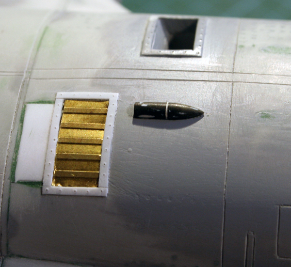
Tired of sanding the fuselage/wings/enginecovers/intakes, I worked a bit on one of the Aden pod. They some more detailling. FP provides some part such as the muzzle but more was requested and done mainly with styrene, after sanding, filling the rivets and proper re-engraving. Some holes were also bored through. I should have made some bumps a little bigger but my 2 component putty was dry in storage :) Beside, I usually suck at that task. The good and the ugly :)
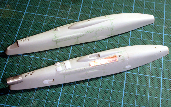
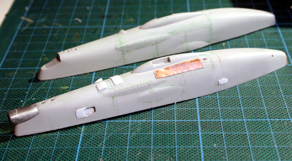
I used some holidays to detail the fuselage with PE, and other addition.
I was surprised at the amount of mistakes the Flightpath kit made on this set? I'm usually quite used to their instructions and use their kits a lot, but here, there was a lot of problems...
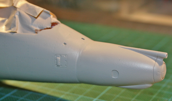
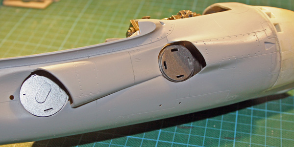
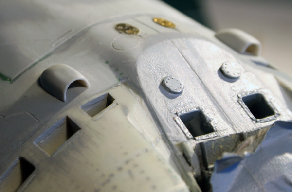
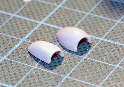
First I started by reshaping the two aircon ram air intakes. they are way too round in the kit to my liking, so I made them much angular.
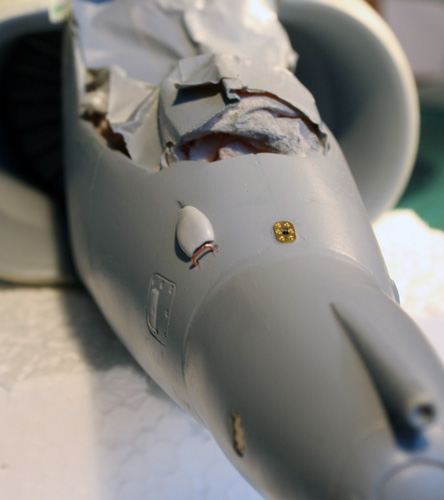
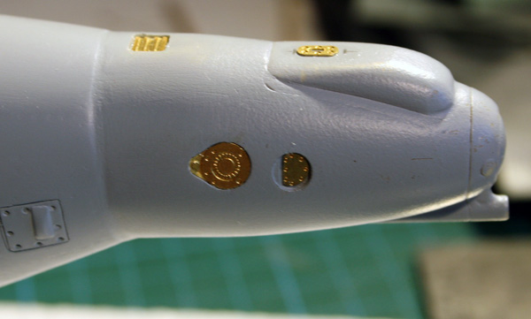
The resin nose was detailled as well, no problem here, just PE parts and kit parts. I just added the forward edge of the intake in rod.
The resin intakes are nice but I was bothered by the middle door being fully closed. I decided to dig into it to give it a slighly closed effect. I hope that one gives good result after painting?
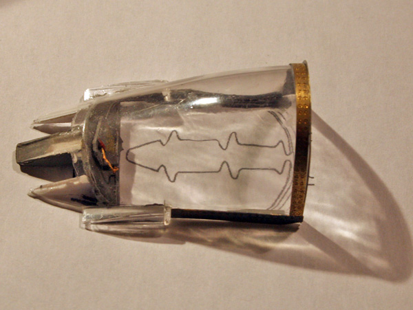
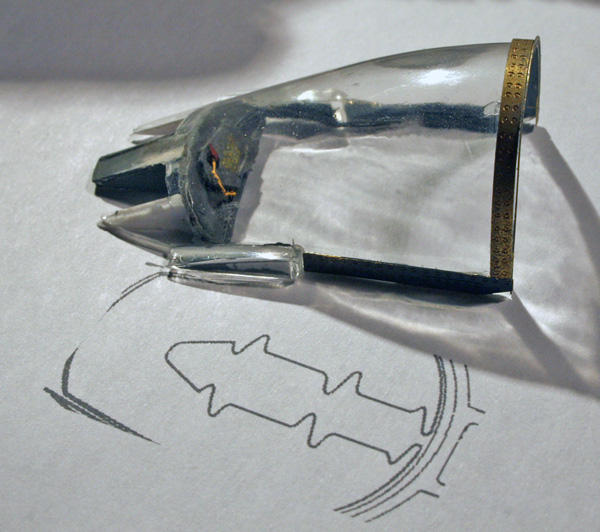
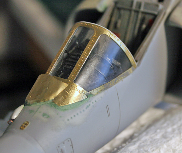
One of my biggest challenge is the canopy. It was completely sanded down, polished and klired. Then I started detailling the canopy with PE frames and sliding parts at the back. Those PE parts are completely wrong (Or I was too dumb to install them correctly) Whatever I tried, I ended up with a non connecting rear canopy with the back too high than it should be. The PE parts were fine but couldn't stand the comparison to real pictures, so I decided to redo that part in styrene.
The rear plate of the canopy with the MDC control box has been done in scratch as all additional kits lacks it.The forward windshield is a nightmare as well. It has to be cut so the PE frames & wiper housing can be added. Cutting it make the joining to the fuselage almost impossible. And of course the canopy break a bit too far when I cut it. Big Big messup.
I had to rework a bit the glareshield so it wouldn't conflict in height with the windshield. The glareshield can't be placed too forward either otherwise the windshield doesn't rest rearward enough. The vertical frame of the windshield should come right at the angle of the fuselage line. Luckily, the PE frame will make the junction between the transparent plastic and the fuselage and cover any hole. There's just one point forward right where I lack some transparent plastic. Not sure How I'll solve that one.
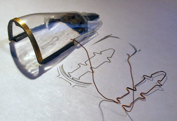
Some more work doing the MDC for the canopy.
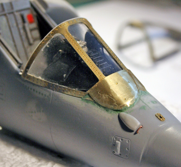
I was about to give her a coat of primer again, but decided I'd better fit the windshield first, which I knew would give me trouble and sure it did. The kit part was ready and klired but although I worked with gloves all the time, the transparent suffered quite a bit in the process.
I started by gluing the front PR frame to the kit windshield that was cut too shape (a bit too much as I reported) then the assembly was glued to the airframe. Making sure I had good contact on the forward edge and on the pilot side. Those are the main three points of contact, the only ones were I used superglue.Then I fitted the side frame, along the fuselage each side of the windshield. that covered some nasty gaps so all was fine. I just had to take care the connecting between the side nad top PE parts went smooth and some PE cutting was required there. the PE part is too long as well, I had to remove 2mm from each side.
Then the boundary between the plastic and the PE was given a coat of putty quicly sanded.
At that point I was pretty happy and though it was over... then I realised there was no specific instruction for the wiper housing in the FP instructions. Well, there's no clean bends on that one, so hard to make instructions I guess... So armed with some pictures I bent the part, glued it in place (using the lack of rivets ont he PE frame which gave me some hints were the housing needed to go and again applied some putty on the edges)
It looks to me that the housing may be a bit overdone, but I'll have to live with it...
I may have to remove that forward vent and replace it correctly ...
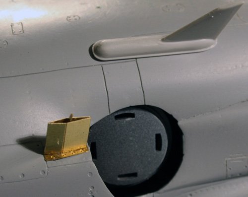
Moving on to the bottom's fuselage:
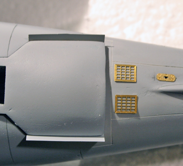
On the bottom pix, you see the extra panel provided by FP and where the instructions place it. It's behind the airbrake when it's closed ...
On the top pix, I placed the dispensers like I think they should be.
It seems the FA2 airbrake is shorter and the dispensers are more forward than on the FRS1 & GR3
Still am not decided for that extra door, I might keep it for the scrap box, not sure ...
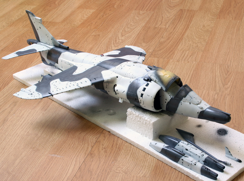
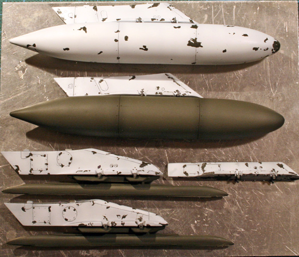
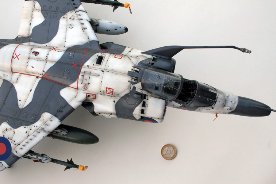
Detailling the airframe was finished, so I started painting ... finally.
First, the regular camo made of green H330 and grey H331.
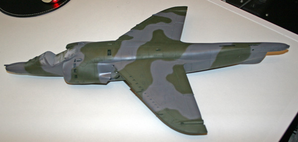
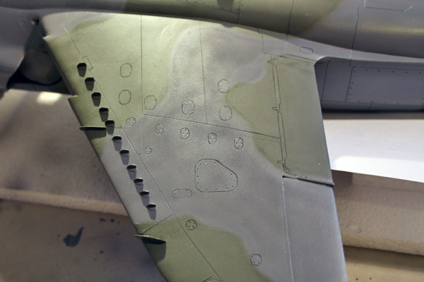
Looks dull, isn't it? So as usual, I'll apply my favorite technique by lightening the centre of the panels with the same grey + white. Here's the wing before and after:
It's good to be painting after such a long while working plastic and PE.
I usually always handbrush my camo with no masks, but the harrier seem to have pretty strong edges between the green and the grey. Since the pattern and number of coulours involved are important : greay base / grey + white / grey + Mr Colour / green base / white .
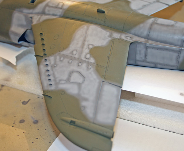
I'll try the bluetack technique which I never tried before to protect the grey parts of the camouflage already painted.
Once the bluetack rolls were applied, the remaining of the grey was masked with papers and maskol was applied on the green here and there to provide peeling & scratching effect of the white wash.
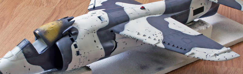
The bird is ready for his snow coat ...
In the meantime, I realised I lost a part. One of the outrigger part and after having checked the whole room and the vacuum cleaner, I decided to redo one from a bit of resin support.
It's not casted, it's carved in hard resin. Much easier than I though and the result suits me just fine:
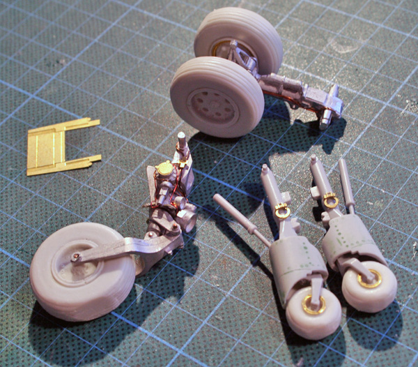
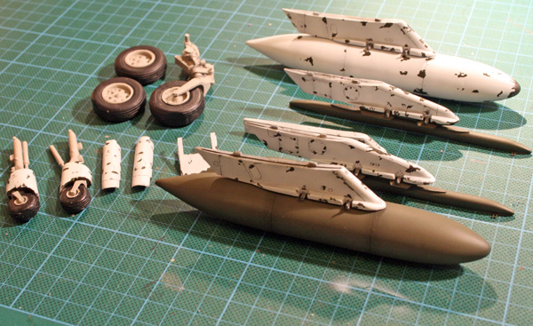
And finally all gear parts almost ready for painting.
I used the PE set from Flightpath for the PE details and the main gear and nose wheel legs, the Heritage resin wheels (the legs are really too much work to clean them)
and some rods for the brake lines and electrical wires instead of the 2dimensional PE which I feel is not up to it.
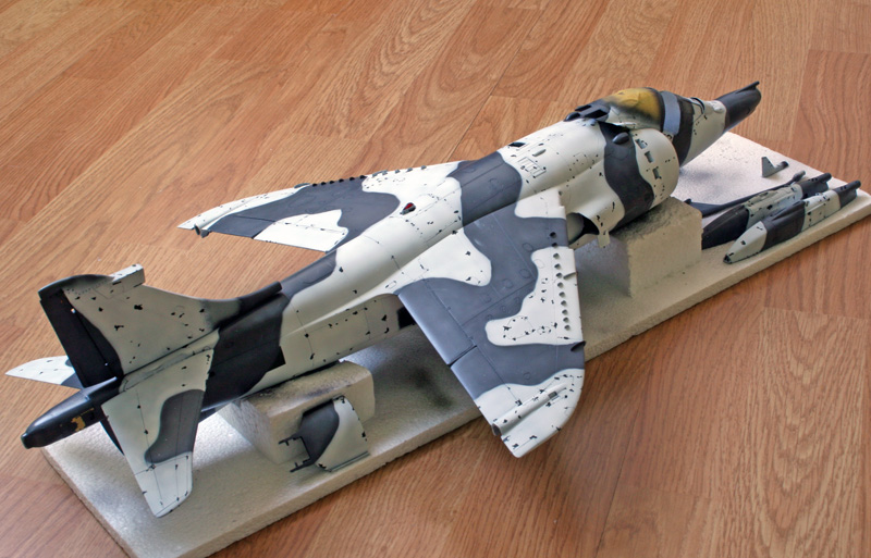
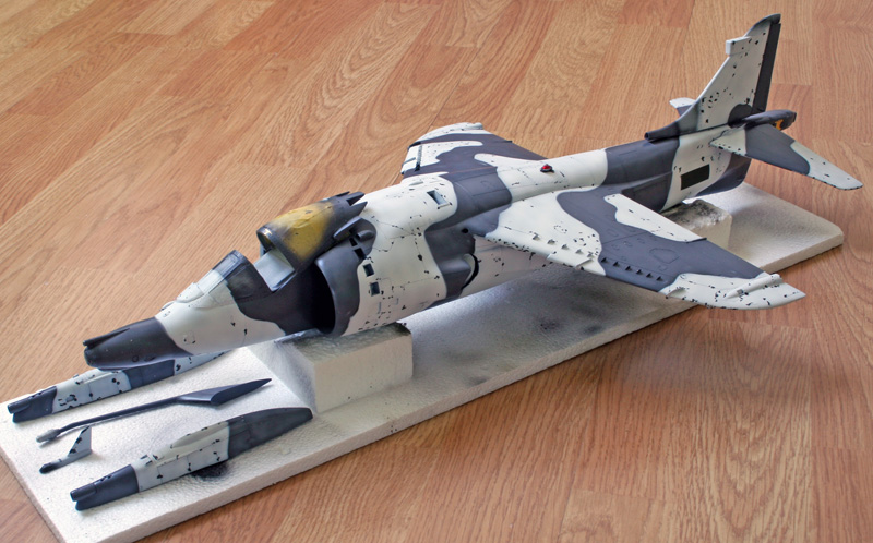
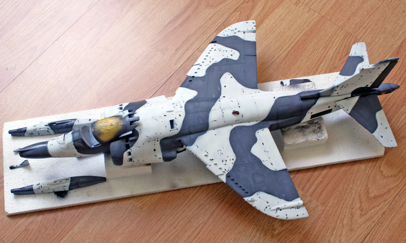
Onwards with painting...
The grey was protected with rolls of bluetack and then paper, I used maskol for chipping effect on the green and finally I spent a 4 hours session painting white, fighting the fresh blue tack that sticks to everything it touches ... It wasn't easy.The good thing by painting white over dark green is that I could make a post shading effect by spraying less white above the panel lines. We don't see this effect very well in the pictures, but it looks very good and subtle in real. All in all it was a race against time to get her done quick before the bluetack damaged the grey or before the maskol couldn't be removed easily. Was't sure about any of the two possibilities, but I wasn't going to take any chances.
But I'm pleased with the result, i still have some grey to correct here and here but I start to see the end of it :)
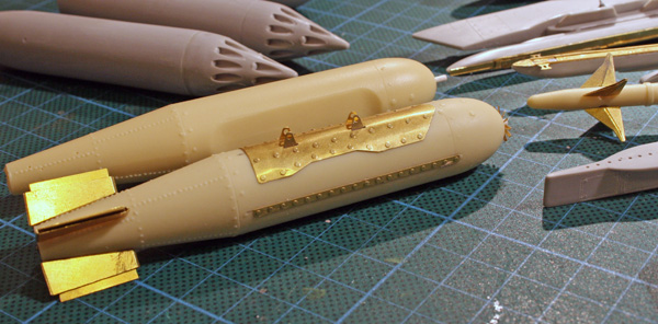
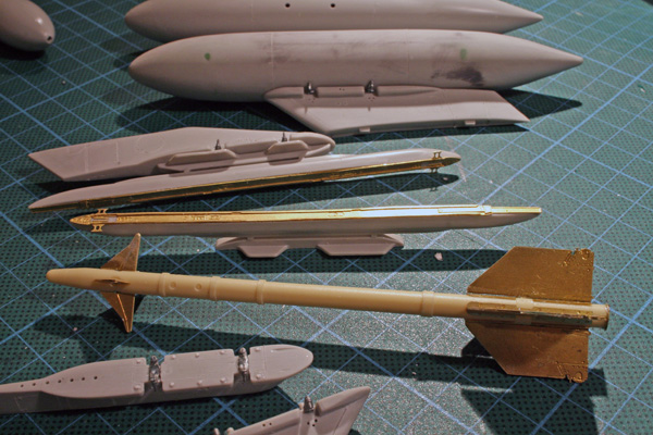
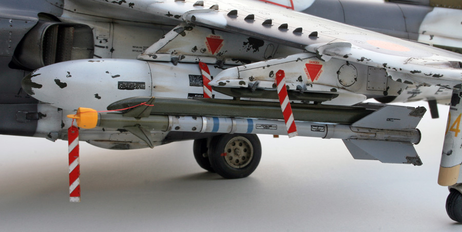
The pylons needed a lot of detailling as they are completely blank. The BL755 and AIM9 comes from the FP kit and both are very well detailled. The sidewinder is a model in itself, but very well designed, Kudos to FP.
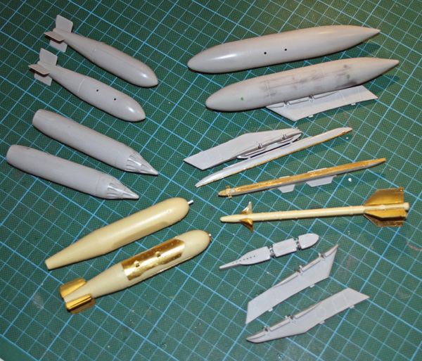
I assembled the kit's weapons as well, not sure what I'll do with them, but at worst, I can use them on the dio somewhere. The current plan is to have the centerline empty, inboard stations with the BL755 or tanks and outboard stations with the aim9 or BL755. I'm still retaining the possibility to switch stores :)
Still need to make the second BL755 and sidewinder.
Although they would be good enough for a 1/32 kit job. I cut them in two and glued them on the side of their pylon, which tends to hide their small sizes.
Next step was to paint the pylons and wing bags green, then maskol and then overspray in white.
The second wing tank will remain green and was given a lightening coat of green, same technique as for the gray in the early painting.
That will give one wing tank white, the other taken from a bird that wasn't dressed for winter. I almost decided to use the navy blue instead, but decided against it at the very last moment.
I knew about the model's gear problem from reading other builds but I hoped that using the after market gear legs would make the problem less worse. Well maybe it is less worse, but I still need about 3.5mm for the outriggers to touch ground, and that's with the outriggers extended at max...
Nothing much can be done in the gear bay to replace the gear legs position notches, too late for that.
When you consider building that 1/24 harrier in your stash, consider solving this BEFORE closing the fuselage (easier said that done ...)

Basically, the main gear should be 3.5mm higher in the fuselage, but that will dangerously place the wheels against the bottom of the Aircraft.
Nose wheel need to be deeper inside as well otherwise the angles of the aircraft will be wrong on the ground ...
There we go .. All four contact points on ground. just placed for test fitting, no glue yet as some minor details need to be worked on.
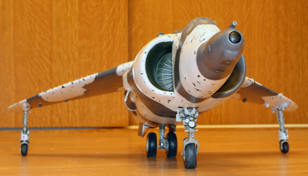
Sanding a bit more the mains, turning the sanded flat part of the outrigger on the upper side of the wheel and boring a lower center hole in the main wheels for the axe did the trick.
I can't say the aircraft identification within the RAF is simple. But I narrowed my list of possible birds to just a few:
1st sqn Red 09 XV964
1st sqn Red04 XV752
1st sqn Yellow 04 XZ993
4th sqn Yellow M XZ993
4th sqn Yellow K XZ969 (on airfix GR3 decal sheet)
4th sqn Yellow V XW921
XZ993 is an oddity.
It flew as yellow 04 in the first squadron, then was transferred to 4th squadron as yellow M
Haven't decided which one to pick so far, the only thing I know for sure is that Red 04 XV752 had indeed been deployed to Norway. Still I like the 4th squadron badge much more.
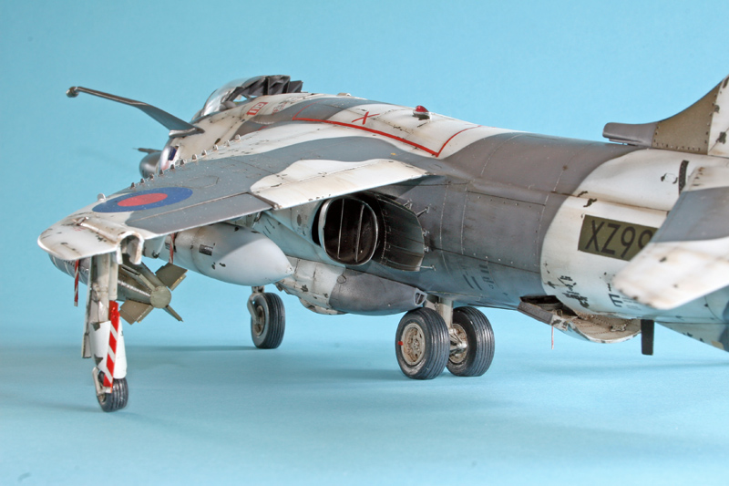
The only picture of a 4th sqn deployed to Norway I found was for XZ999 tailcode I but there certainly are others.
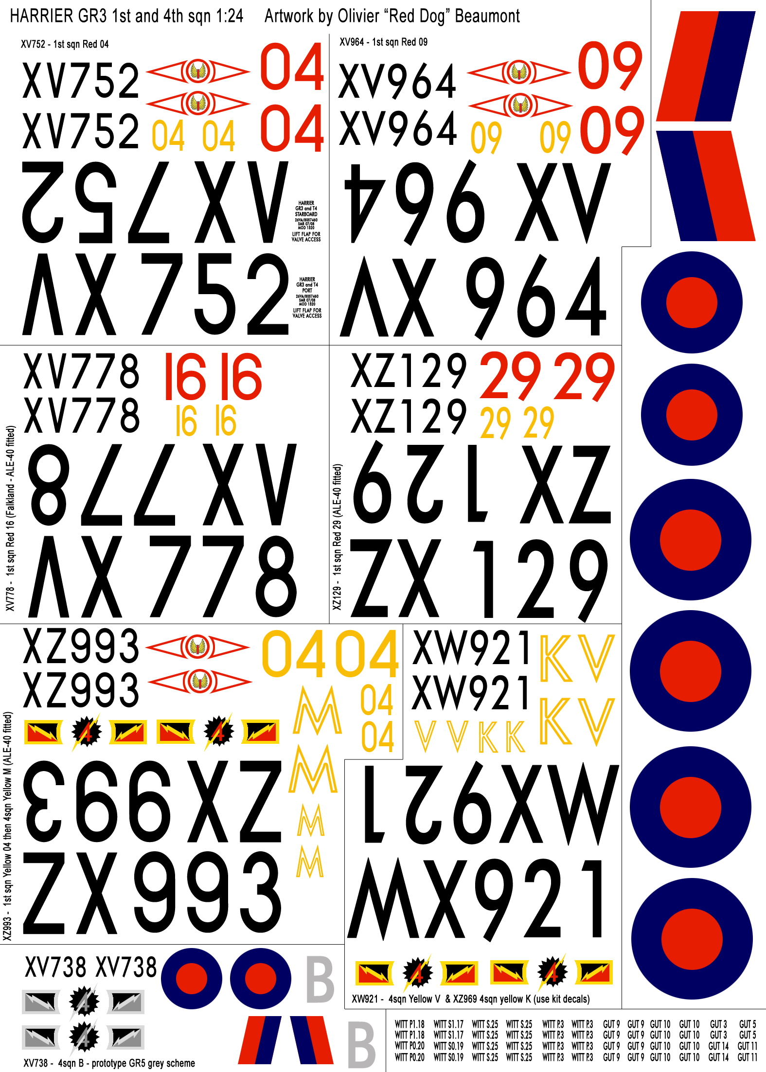
Here's the prototype of the soon to be printed homemade decalsheet ...
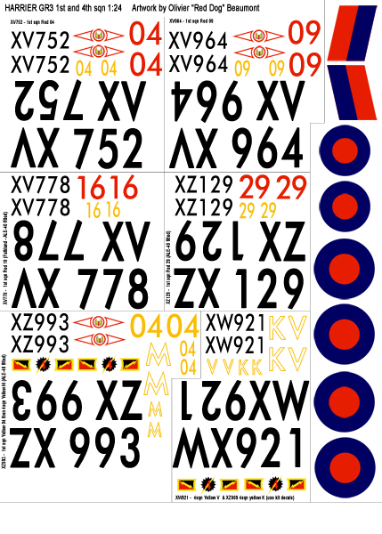
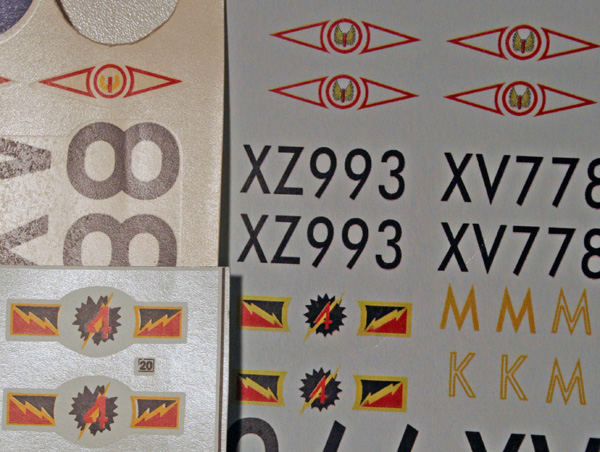
The decal sheet has been printed:
Here's a rough comparison between the kit decal's and the homemade sheet.
I'm very lucky all those light colors (and white) are placed on white camo paint - I might just get away with it!
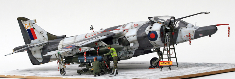
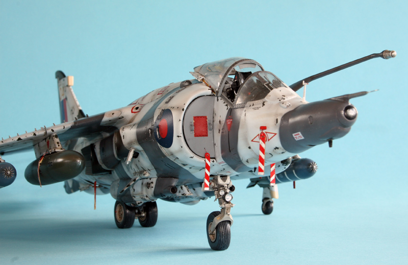
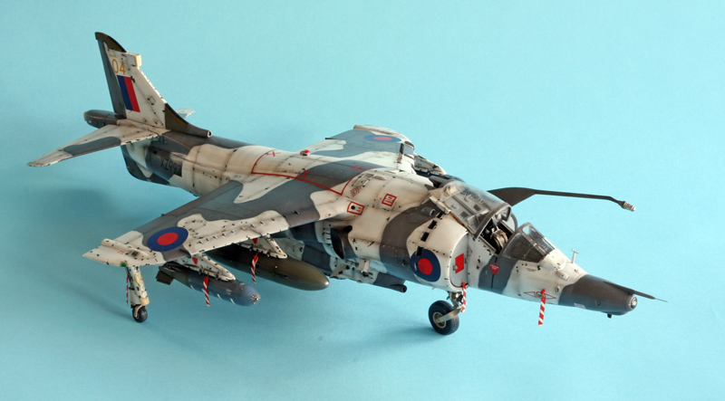
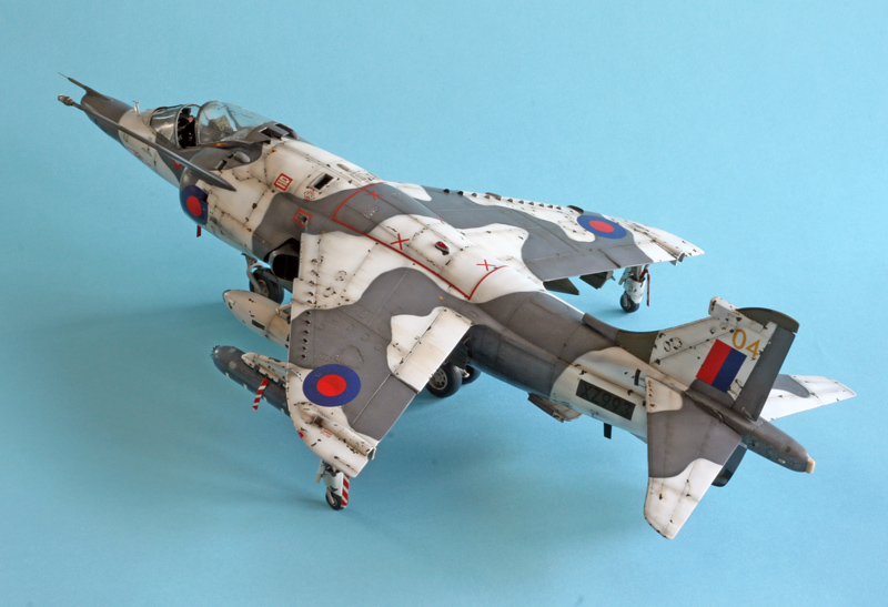
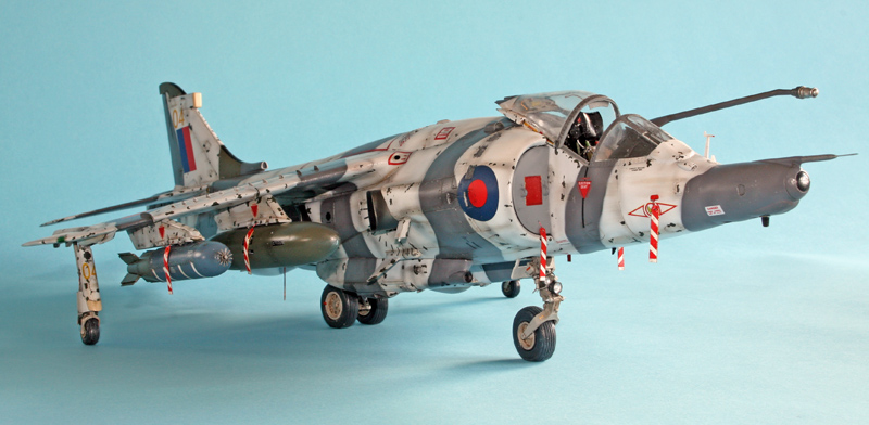
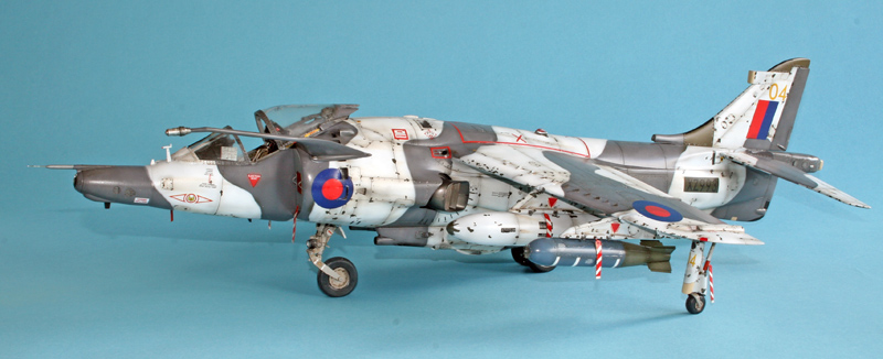
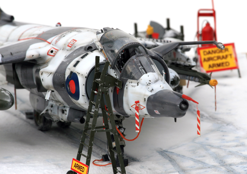
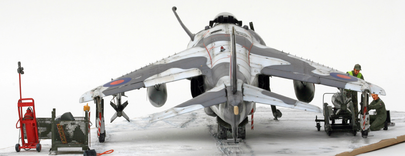
The model is finished and ready for the diorama:
On with the diorama
Some more goodies in PE, scratch and resin from different sources :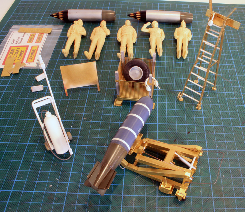
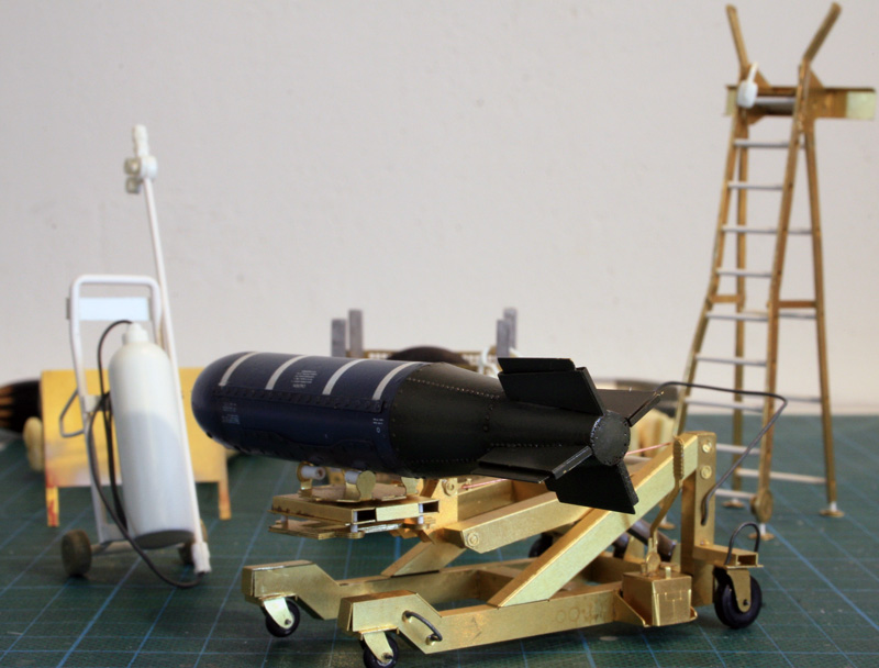
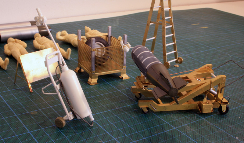
The Y loader is PE from Flightpath, as is the ladder, the FOD bin and other small goodies.
The extinguisher is scratched. The resin figures are from the trumpeter Spitfire but I don't think I'll use them. they are too stiff. Instead, I think I'll use some 1/24 F1 mechanics.
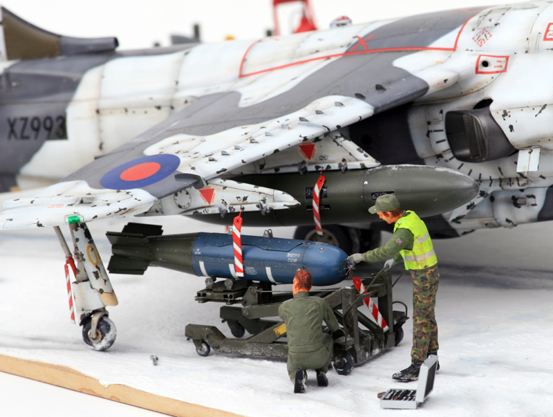
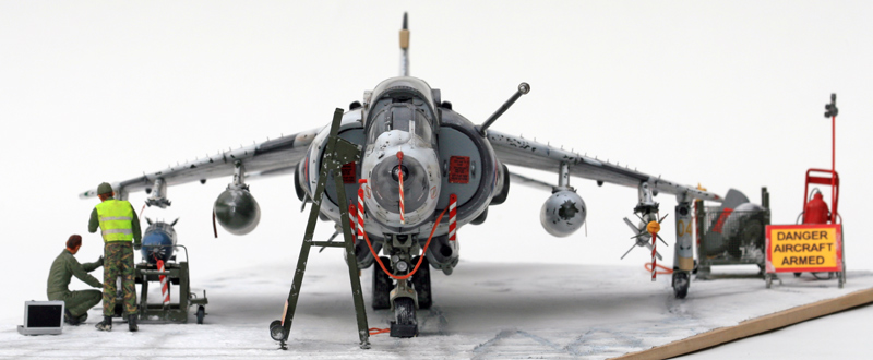
Some pictures of the final arrangements:
The artwork for the decal sheet is available:
Different marking options for green/grey - Wintercamo and the experimental all grey scheme.
http://www.ravico.com/ST/models/harrie...er_GR3_1-24.pdf
Model finished in June 2011 after 3 years building.